Week 2- 2R Robotic Arm Challenge
AIM: To write a program to simulate the Forward Kinematic of a 2R Robotic Arm in Matlab.
OBJECTIVE:
- To solve and simulate the forward kinematic of a 2R Robotic Arm and understand the movement of manipulator.
- To create the animation of working of a 2R Robotic Arm.
INTRODUCTION:
A robotic arm is a robot manipulator, usually programmable, with similar functions to a human arm. The links of such a manipulator are connected by joints allowing either rotational motion(such as in an articulated robot) or translational(linear) displacement. The link of the manipulator can be considered to form a kinematic chain. The use of industrial robot is increasing in areas such as food, consumer goods, wood, plastics and electronics, but is still mostly concentrated in the automative industry.
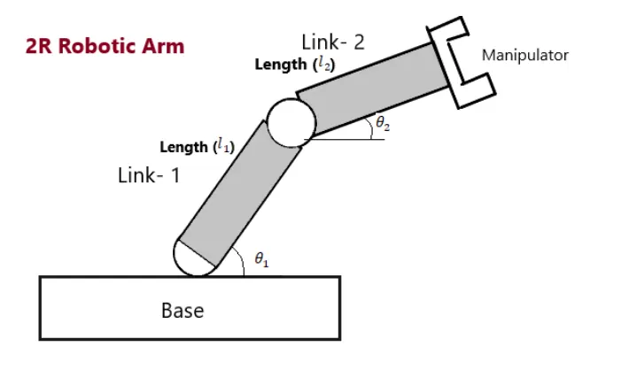
In the image shown above, the robotic arm consists of 4 components,
- The Base, which is clamped to the surface and all other links are joined through hinge joint.
- Link1(L1) making `theta1`with horizontal.
- Link2(L2) making`theta2`with horizontal.
- The device attached to the manipulator which interacts with its environment to perform tasks is called the end-effector.
INPUTS:
- For our program we have assumed the length of link 1 and link 2 to 1.25m and 0.75m.
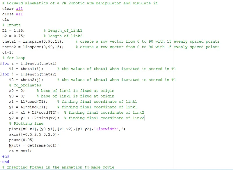
- In order to simulate the robotic arm it is necessary to vary `theta1`and `theta2`to obtain a desired animation and it cannot be possible if we manually enter the respective data everytime. so we have created a row vector from 0 degree - 90 degree with 15 evenly spaced points between them.
- The coordinates of base,i.e is assumed to be at origin (0,0)
- The coordinates of end points of link1(L1) can be found by using trignometry as, x1 = L1.cos(`theta1`) y1 = L1.sin(`theta1`)
- Similarly, the coordinates of end points of link 2(L2) can also be found from trignometry as, x2 = x1 + L2 cos(`theta2`) and y2 = y1 + L2. sin(`theta2`)
MATLAB CODE:

RESULTS:
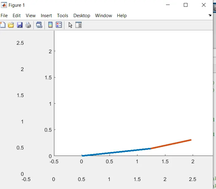
- The following plot is obtained as the output.