Week-7 Challenge: DC Motor Control
Aim:
1) ‘Speed control of a DC motor using BJT H-bridge’.
- Comment on the armature current shoot-up from the scope results.
- Refer to the help section of ‘The Four-Quadrant Chopper DC Drive (DC7) block’. Compare it with the H-bridge model.
2. To develop a 2-quadrant chopper using simulink & explain the working of the same with the relevant results.
3. Explain in a brief about operation of BLDC motor.
Explaination:
*‘Speed control of a DC motor using BJT H-bridge’.
In the MATLAB / SIMULINK documentation, we can search for the simulation model of the 'Speed control of a DC motor using BJT H-bridge’.
It is used to generate a chopped voltage and to control speed of the DC motor. This model can be opened in Simulink from the documentation itself. As the name suggests, it uses a BJT (Bipolar Junction Transistor) which is a type of transistor that uses both electrons and holes as charge carries, hence the name bipolar. Other transistors such as FET's (Field Effect Transistor) are unipolar transistors meaninig that they only use one type of charge carrier. BJT's are used for switching and amplifying applications. BJT's have 3 terminals which are: The emitter(E),the base(B) and the collector(C). Current flows in only the emitter and the collector by the base. BJTs use semiconductors in their working.
There are 2 types of BJT:
- NPN Type
- PNP Type
PNP Transistor:-
This type uses 2 p- type semiconductor and 1 n-type semiconductor. The n-type semiconductor will be the base of the transistor. The emitter terminal is more positive in relation to the collector and base terminals. The collector is connected to positive supply and emitter is connected to negative supply. The base terminal is supplied with voltage and it operates the transistor by switching between ON or OFF state. When the base voltage decreases with respect to the emitter voltage, the transistor is in the ON state.
NPN Transistor:-
This type uses 2 n- type semiconductor and 1 p-type semiconductor. The p-type semiconductor will be the base of the transistor. Construction wise it is exactly the same as the PNP type having 3 terminals. Just as in the PNP type, The collector is connected to positive voltage supply and emitter terminal is connected to negative voltage supply. The base terminal is supplied with a voltage and control the transistor being either is an ON or OFF state. When the base voltage increases with respect to the emitter voltage, the transistor is in the ON state.
BJT-H Bridge:-
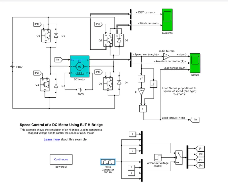
When the BJT is conducting i.e. operating in the saturated region, there will be a forward voltage developed between the collector and the emitter (in the range of 1V). An IGBT is used to model the BJT because of this. The switch is controlled by a simulink signal. The DC motor is used in this model is pre-set to with specification: 5HP, 24V, 1750rpm. It simulates a fan type load where the load is proportional to the square of the speed. The mean armature voltage can be varried between 0 to 240V when the duty cycle is changed anywhere from 0 to 100%. The duty cycle can be changed from the pulse generator block.
The H-bridge consists of 4 BJT and diode pairs. Two transistors are switched on simultaneously: Q1 and Q4 or Q2 and Q3. When Q1 and Q4 are fired, a positive voltage is applied to the motor and the diodes, D2 and D3 operate as a free wheeling diodes when Q1 and Q4 are switched off. Similarly When Q2 and Q3 are fired, a negative voltage is applied to the motor and the diodes, D1 and D4 operate as a free wheeling diodes when Q2 and Q3 are switched off.
By default, the motor will start in the positive direction and has preset duty cycle of 75% with a mean DC voltage of 180V. At t = 0.5 seconds, the armature voltage will reverse and the motor will run in the negative direction.
This is the SIMULINK MODEL for the BJT H-Bridge used in the speed control of a DC motor:
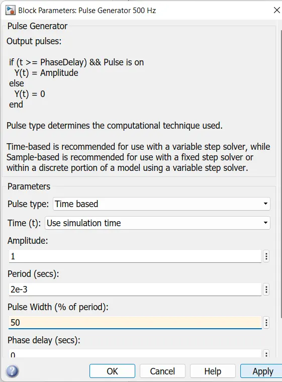
Here, we can see the "Pulse Generator 500Hz' block. If we open it, we will get a dialog box with its setting which is shown below:
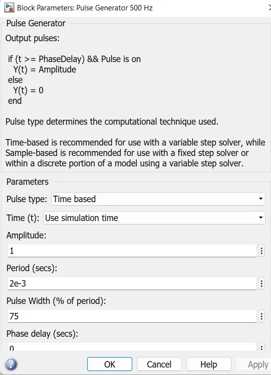
As we can see, that pulse generator is already prese with some settings. The pulse width field allows us to modify the duty cycle of the motor and hence we can prevent the motor current from shooting up when the motor changes its direction from forward to reverse by default the duty cycle is 75% meaning that the voltage is supplied to the motor for 75% of the time for one cycle. For the remaining 25%, the motor is off and receives no voltage from the source. It is this alternation between the ON and OFF states, that allows us to vary the voltage that is supplied to the motor and there by control the speed of an electric vehicle.
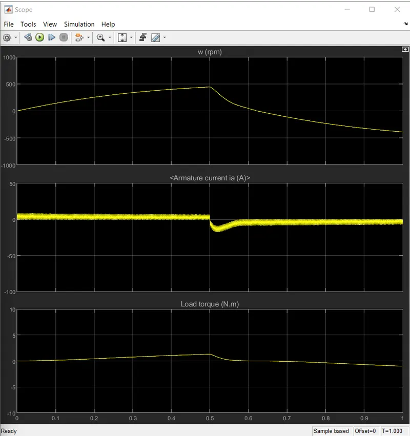
The image below shows the output of the scope when the simulation is run using the preset values in the pulse generator block. There are 3 output graphs of angular speed, armature current and load torque all against a time axis.
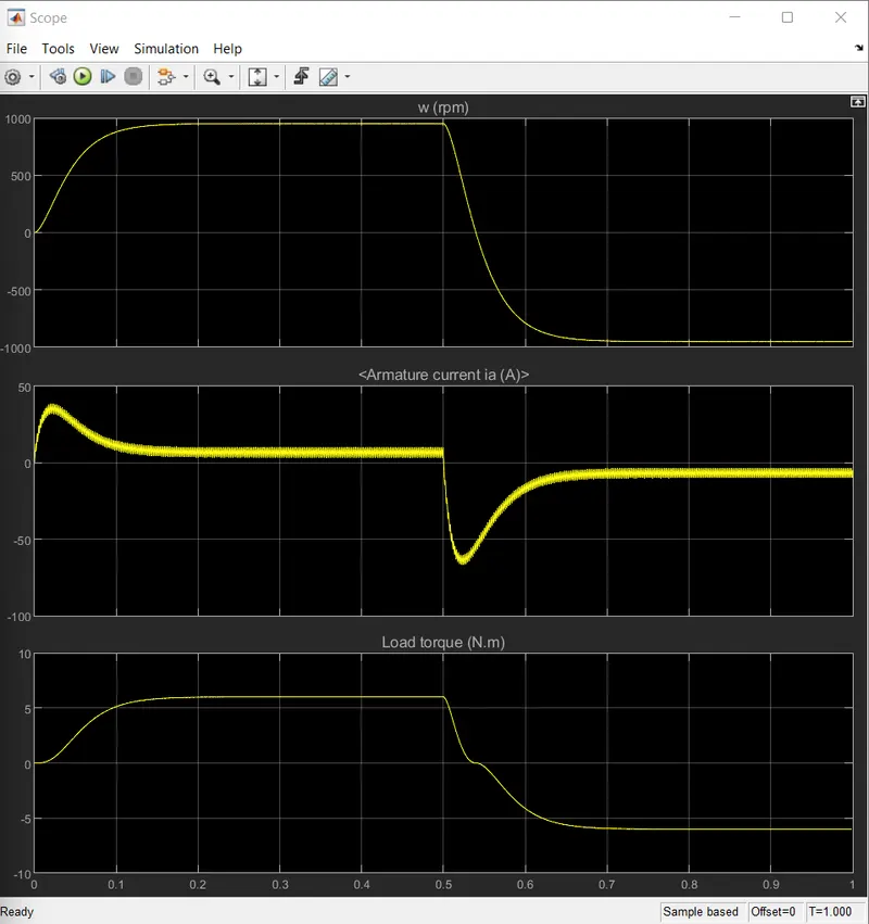
For this for this question, we are intrested in modifying the simulation in order to prevent the initial shoot up of the armature current at the start of the cycle. This shootup occures whenever the armature voltage reverses direction which is every 0.5 seconds. In the second graph above (which shows the armature current vs. time) we can see that at the sart of the cycle, there is sharp increases in the the armature current that then decreases an comes to a more stable level where it remains until 0.5 seconds. When the next cycle begins, the exact same effect occures but in the negative axis because in this cycle, the armature voltage is reversed.
This frequency of reversing the voltage direction has been preset in the 'armature voltage control' block. Opening it will give you a dialog box of its setting where the 'step time' field controls the frequency at which the voltage is reversed.
If we change the duty cycle i.e. the pulse width, we can controls this initial shootup of the currnt that occures every time the armature voltage direction is reversed. When the duty cycle is decreased to 50% the output graph that is obtained is shown below:
Result:-
For the 50% duty cycle, we can see that armature current does not shootup initially for the positive direction of the armature voltage. However, after the 0.5 second mark when the armature voltage reversed, the armatur current shoots up in the negative direction. so we need to decreases the duty cycle further to prevent this.
1.c) The DC7 Four Quadrant Chopper DC drive model is as indicated below:-
image
The Four-Quadrant chopper DC drive (DC7) block represents a four-quadrant, DC- supplied, chopper (or DC-DC PWM converter) drive for DC motors.This drive features closed-loop speed control with four quadrant operation. The speed control loop outputs the reference armature current of the machine. Using a PI current controller, the chopper duty cycle corresponding to the commanded armature current is derived. This duty cycle is then compared with a swatooth carrier signal to obtain the required PWM signals for the chopper.
The Four Quadrant Chopper DC drive block uses these blocks from the Electric Drives/Fundamental Drive blocks library:
- Speed Controller (DC)
- Regulation Switch
- Current Controller (DC)
- Chopper
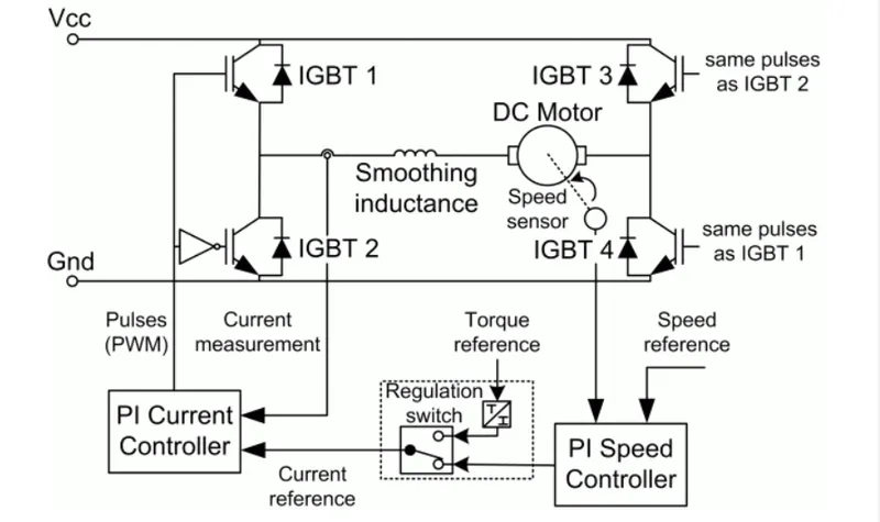
It has a 3 phase power source with 380V 50Hz , the converter is fed by 515V DC and then AC to DC Converter that transfer the energy to the chopper drive which transmitts the power to IGBT 1 & 4 and IGBT 2 & 3 which then follows the duty cycle and following them are the Armature Voltage, Armature Current respectively.
The overall difference and comparison of the Four-Quadrant Chopper DC drive (DC7) are H-Bridge model are as below:
| Four Quadrant Chopper DC drive | H-Bridge Model |
| Four Quadrant Chopper is a Pulse Width Modulation Converter | Works on the input signal of the Pulse Width Modulation and thus gives the output |
| Uses 2 pi controllers to commanding the armature current | If the value is more than Enable Threshold Voltage the output value is equal to the output oltage Amplitude. |
| Has the quality of the operating in all 4 quadrants (Forward, Reverse, Forward Regeneration, and Reverse Regeneration) | If the value is less than Enable Threshold Voltage the output valueit maintain the load circuit using the freewheeling mode option |
| High switching frequency DC-DC converters | The simulation mode parameter assists in accuratevalues, when the assumptions are added. |
| Blocks that it uses (speed controller, Regulaion Switch,Current Controller,Chopper) | Tempreture difference and Thermal Port parameter are also added for better simulation |
| Simulation time is less | Simulation time is more |
| Widely used in Automobile | Widely used in Robotics |
Question 2) Two-quadrant chopper
Circuit Diagram For Two Quadrant Chopper:
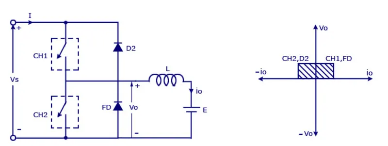
Two quadrant chopper is also called as type C chopper. Type C chopper is obtained by connecting type -A and type -B choppers in parallel. We will always get a positive output voltage Vo as the freewheeling diode FD is present across the load. When the chopper is on the freewheeling diode starts conducting and the output voltage Vo will be equal to Vs. The direction of the load current io will be reversed. The currentio will be flowing towards the source and it will be positive reagardless the chopper is on or the FD conducts. We can say the chopper and FD operate together as type -A chopper in first quadrant. In the second quadrant, the chopper and D2 will operat together as type -B chopper.
The average voltage will be always positive but the average load current might be positive or negative. The power flow may be line the first quadrant operation i.e. from sourceto load or from the load to source like the second quadrant operation. The two choppers sould not be turned on simultaneously as the combined ation may causes a short circuit in supply lines. Foe regenrative braking and motoring these type of chopper configuration is used.
TWO QUADRANT CHOPPER MODEL USING SIMULINK:
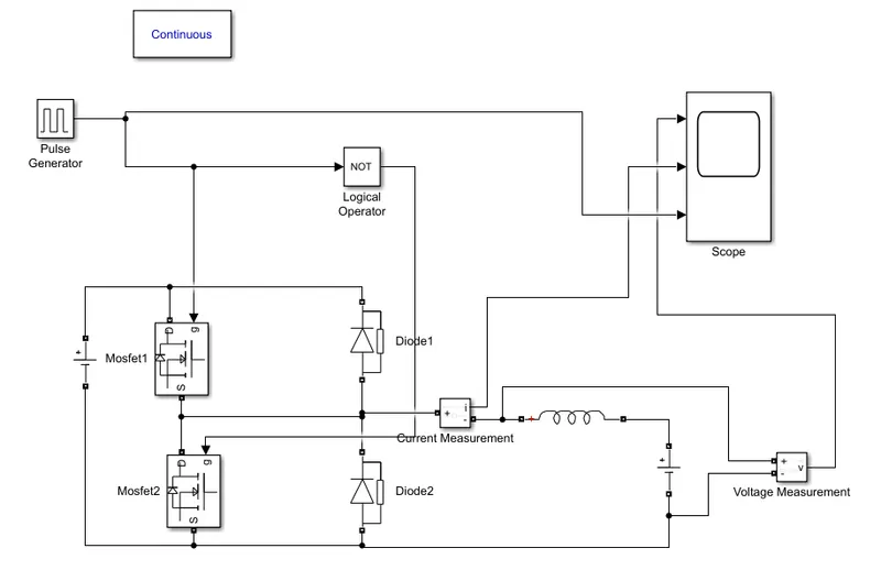
Let us take two mosfet blocks and diodes blocks and connect it as shown in circuit diagram.
the dc voltage source is cnnected as shown.
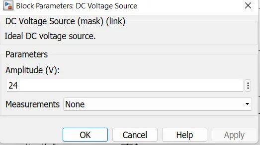
let the voltage of dc voltage source be 24 volts.
let us consider an series RLC branch block and slect inductor L. Thus block works as a load.
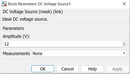
To consider LE load i.e. motor load and dc voltage source of 12 volts is also connected in series with inductor.
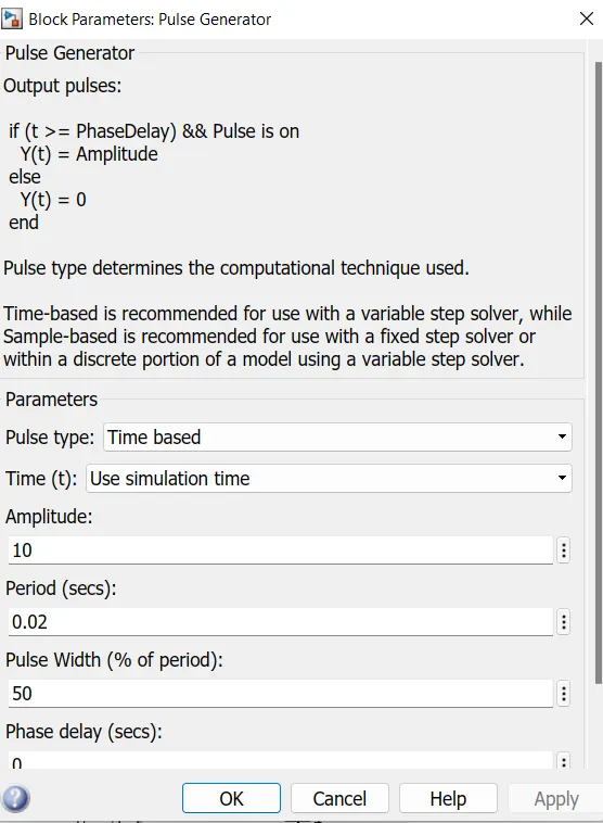
The pulse generator is used to create gate pulse. The not gate is used in the model so that the two MOSFET will not get closed at the same time otherwise short circuitwill occure due to use of not gate, when MOSFET is ON the other MOSFET will get OFF and other MOSFET is ON the first MOSFET will get OFF.
The amplitude of pulse generator is kept 10 also that we can clearly see the pulses at scope and let period be 0.02 second and let pulse width be 50%.
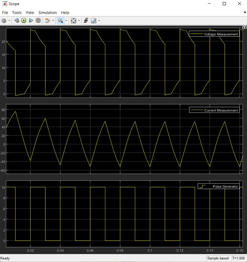
SCOPE RESULT:
The voltage waveform is not going less than zero. the minimum value of voltage is zero and maximum value is always in the positive direction.
however in current waveform, the current increases and dereases. The urrent may be positive as well as negative. and pulse amplitude is 10 thus from pilse waveform we can see that the pulse amplitude is 10.
Question3) BLDC Motor Operation:
BLDC motor named as brushesless dc motor having high efficiency than other types of motors. This motor is also known to be synchronous motor.
Consturuction:
Most of the motors having brushes in their rotor as it transfers current into the rotor circuit. But here differently rotor is placed with permanent magnet.
The stator coil is wouned with coils, they are stationary but producing variable DC voltages for rotating the permanent magnet as changing the magnetic field of stator poles continuously.
The controlling of motor is by changing the magnitude and direction of current flowing thrugh the stator windings.
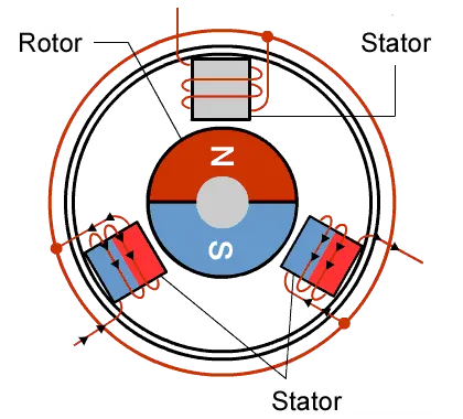
A BLDC motor with three coils on the stator will have six electrical wires (two to each coil) extending from these coils. In most implementations three of these wires will be connected internally, with three reamaining three wires extending from the motor body. Wiring in the BLDC motor case is more complicated than simply connecting the power cell's positive and negative terminals.We will look more closely at how these motors work in the second session of this series.
Operation of BLDC motor:
We can consider three winding terminal are connecting out as U,V,W and their another ends are connected in single point as shown in below figure. The angle shift between two coils makes 120 degree.
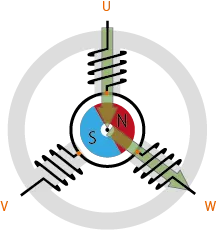
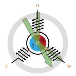
The current moves from U to W makes magnetizing the coils attrats the rotor consisting of permanent magnet makes moment as shown above to align with the resultant arrow (larger arrow).
North pole of magnet towards arrow mark of resultant arrow.
Rotational is maintained by continually switching the flux so that the permanent magnet is constantly chasing the rotating magnetic field induced by the coils. In other words, energizing of U,V and W must be continually switched so that the resultant flux keeps moving, producing a rotating field that cintinually pulls on the rotor magnet.
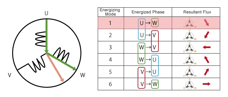
The above movement are acheived by continuous change in current direction oer two ploes of stator at single time. But this is slightly not continuous in their rotation.
This makes motor vibration and noise will be produced.
So, to attain smooth continuous change in current flow in all stator poles a same time in 120 Degree phase shift.
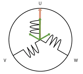
As we have seen, we drive BLDC motor's by continually changing the directionality of the flux produced by the coils. The permanet magnets on the rotor continually change the shifting rotating magnetic field, causing the rotor to run.
This is the working of BLDC motor.
Advantages of BLDC motor:
* One big advantage is efficiency, as these motors can control continuously as maximum rotational force(torque).
* Even small BLDC motors can deliver considerable power.
* BLDC motors can be controlled, using feedback mechanisms, to delivery precisly the desired torque and rotational speed.
* Reduce enery consumption and heat generation.
Control of BLDC motor:
By using inverter circuitry to also adjust the voltage into each coil, we can control the magnitude of the current.
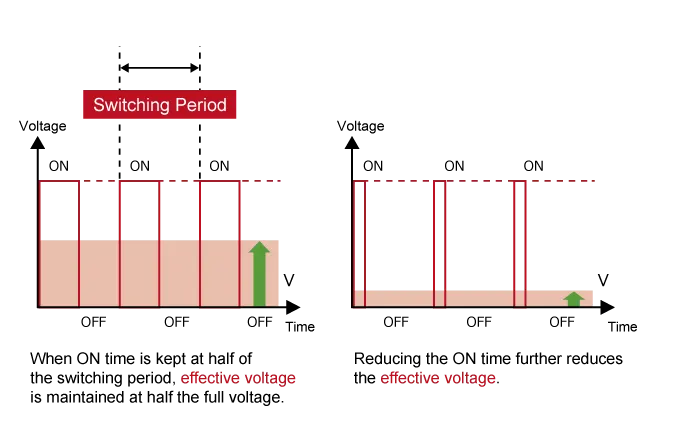
A typical way to adjust the voltage is with pulse width modulation (PWM). We alter the voltage by lengtheninig or reducing the pulse ON time (''Duty cycle'' The ON time expressed as a ratio of the ON+OFF switching interval). Increasing the duty cycle has the same effect as raising the voltage, reducing the duty cycle has the same effct as lowering the current.
PWM can be implemented using MPU's eqipped with dedicated PWM hardware. While 120 degree conducting control only requires two-phase voltage control. sinusoidal conrol uses three phase voltage control and is considerably more complicated as appropriate inerter circuitry is therefore essential for driving BLDC motors.