Week-7 Challenge: DC Motor Control
1.A. Explain a MATLAB demo model named ‘Speed control of a DC motor using BJT H-bridge’.
The model of Speed control of a DC motor using BJT H-bridge is given below
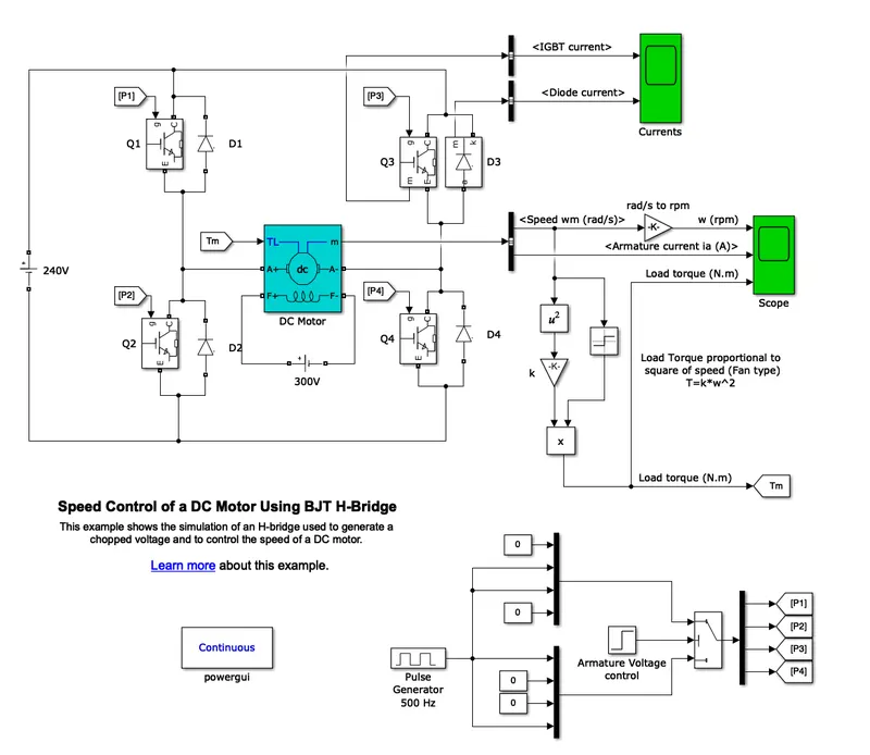
This model is a DC-DC chopper which is used for motor control. BJT H-Btidge model can only operate in two quadrant i.e, quadrant 1 and 2 which means used in forward motoring and reverse motoring. H-Bridge consist of 4 BJT/Diode pairs which are simulated by IGBT models. Out of four transistor, two can switch simultaneouly: Q1 & Q4 /Q2&Q4.
When Q1 and Q4 are fired, a positive voltage is applied to the motor and diodes D2-D3 operate as free-wheeling diodes when Q1 and Q4 are switched off, i.e, forward motoring. When Q2 and Q3 are fired, a negative voltage is applied to the motor and diodes D1-D4 operate as free-wheeling diodes when Q2 and Q3 are switched off,i.e, reverse motoring.
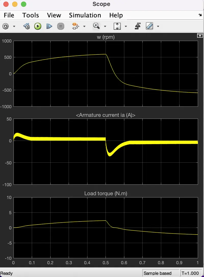
The motor starts in the positive direction with a duty cycle of 75% (mean DC voltage of 180V). At t= 0.5 sec., the armature voltage is suddenly reversed and the motor runs in the negative direction.
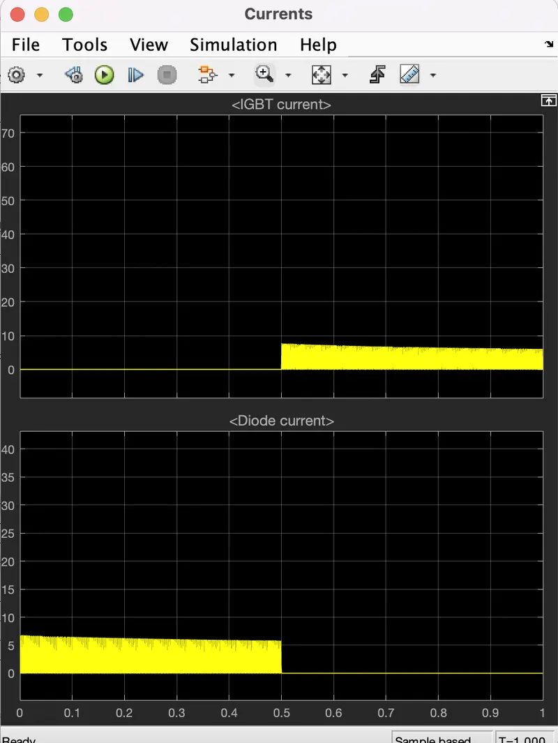
by using scope block we can see motor speed, armature current and load torque and 'Currents' shows currents flowing in BJT Q3 and diode D3.
the simulated results of the above model if the duty cycle is 75%
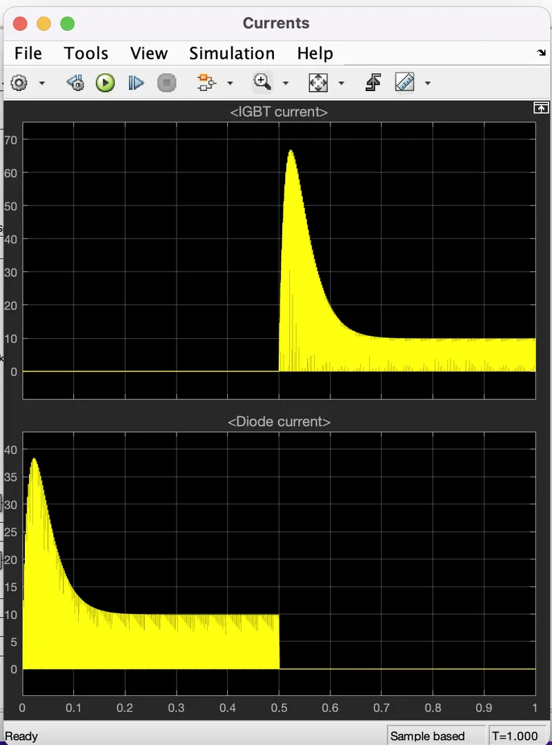
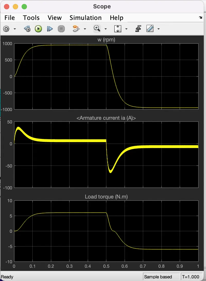
Conclusion:By seeing the scope output, we can see some shoot up happens in the armature current during the change of positive to negative/ negatie to positive in w.
1. B. Comment on the armature current shoot-up from the scope results.
Shoot up: Switching in the circuit leads to heat losses. This heat loss can be dissipated using heat sink material.
In original model duty cycle 75% were used, and we can see shoot up in armature current. so we try to minimise the shoot up current.
For reduction of shoot up we are going to decrease the duty cycle value and check whether improvement is noticble or not.
In the model of speed control DC motor, we try duty cycle with 60%
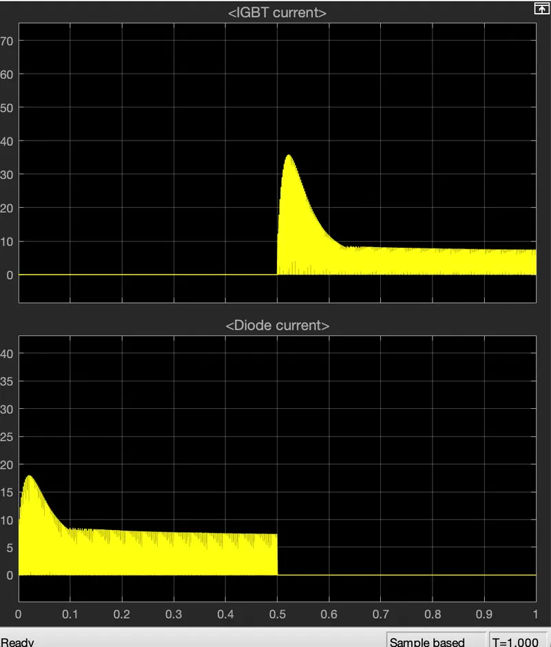
If see the result of duty cycle 60, shoot up is reduced. let us try the model with duty cycle of 40%
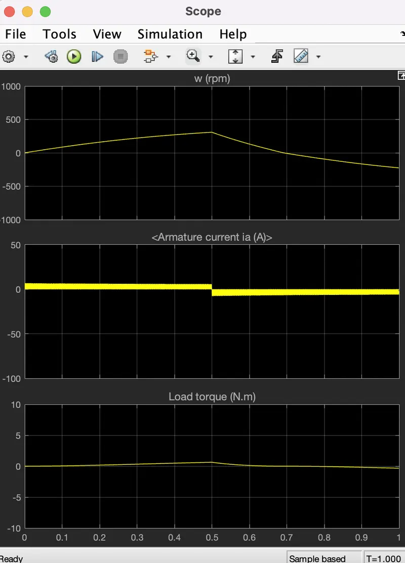
Now smooth change of positive negative in armature current.
Conclusion: Hence by reducing the armature current , we can reduce the shoot up in armature current.
1.C. Refer to the help section of ‘The Four-Quadrant Chopper DC Drive (DC7) block’. Compare it with the H-bridge model.
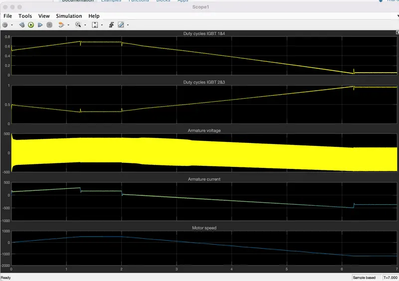
The armature voltage is provided by an IGBT converter controlled by two PI regulators. The first regulator is a speed regulator, followed by a current regulator. The speed regulator outputs the armature current reference (in p.u.) used by the current controller in order to obtain the electromagnetic torque needed to reach the desired speed. The speed reference change rate follows acceleration and deceleration ramps in order to avoid sudden reference changes that could cause armature over-current and destabilize the system.
The current regulator controls the armature current by computing the appropriate duty ratios of the 5 kHz pulses of the four IGBT devices (Pulse Width Modulation). For proper system behaviour, the instantaneous pulse values of IGBT devices 1 and 4 are opposite to those of IGBT devices 2 and 3. This generates the average armature voltage needed to obtain the desired armature current. In order to limit the amplitude of the current oscillations, a smoothing inductance is placed in series with the armature circuit.
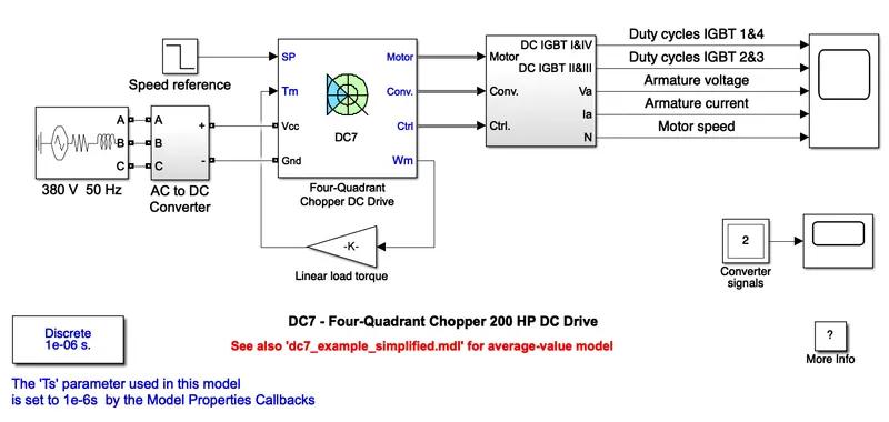
the output of the DC7 model is
H-Bridge:
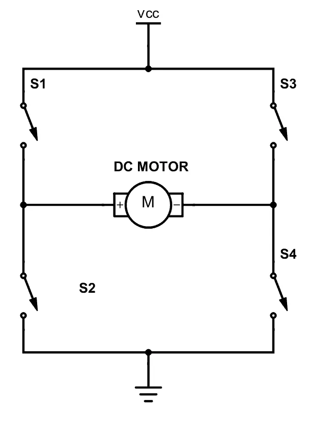
the above H-bridge model has four switch and they work as pair.
s1&s4 work as pair or S2&S3 work as pair.
Forward motoring: If S1 and S4 is used, current flow feom source, S1, load, S4 and ground. load will be positive to negative.
Reverse motoring: If S2 and S3 is used, current flow feom source, S3, load, S2 and ground. load will be negative to positive.
If switch 1,3 / 2,4 is closed then it leads to short circuit of the system.
Comparison of DC7 and H- Bridge
| DC 7 | H- Bridge |
| operates in four quadrant | operates in two quadrant |
| it is an electronic switch | electronic circuits for switching. |
| used in power control | used in motor drive & robotics technology. |
| regenerative braking is there | no regenerarive braking |
| high efficiency than H-Bridge | high efficiency |
| High energy storage. | low loss |
Conclusion: Discussed about DC 7 and H- bridge and then comparison of Dc 7 and H- bridge chopper is made.
2. Develop a 2-quadrant chopper using simulink & explain the working of the same with the relevant results.
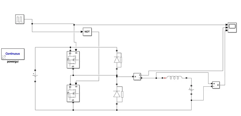
2 quadrant chopper using simulink is going to be modeled.
2Quadrant chopper:
Chopper is a device which is used to convert a fixed DC input into variable DC voltage/ current. In 2Quadrant, the average voltage will always be positive whereas the average load current may be positive or negative. Two switches CH1 and CH2 can not be turned on simultaneously because it will lead to short circuit of the system.
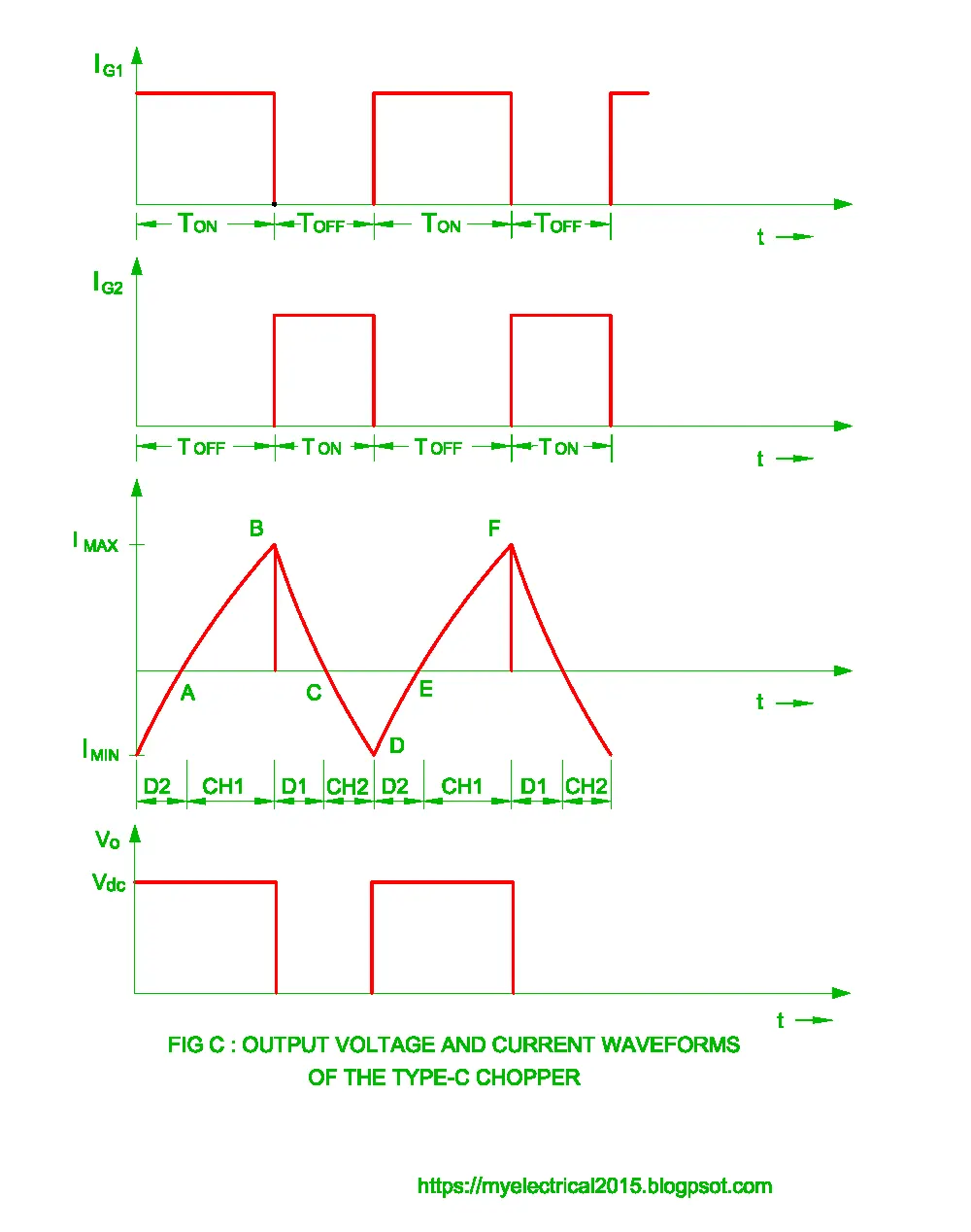
CH1 is on, Current flow through the load and inductor stores energy.
CH1 is Off, freewhelming diode starts conducting & the direction of load current will be reversed. i.e, current will be flowing towards the source.
CH2 is ON, Load current is negative and it uses the path through diode D2.
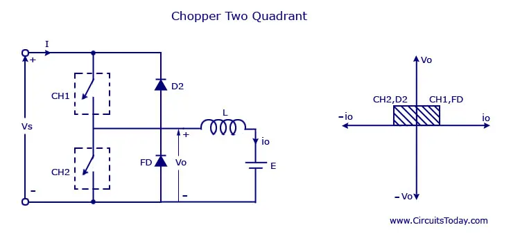
design a 2Quadrant simulink model
- we are to design 2 quadrant model using the above circuit diagram.
- In place of switch, we shall use MOSFET which act as switch. During positive cycle MOSFET 1 will be on, During negative cycle MOSFET 2 will be on.
- Two diode are connected as like the circuit diagram.
- voltage sources are connected. one at input side with 24V and another at output side with 12 v.
- current measurement and voltage measurement blocks are used for the purpose of measuring and its output mapped to scope.
- input signal is given by Pulse generator whose duty cycle is set as 50%, amplitude 10.
Output of the 2Quadrant simulink model is
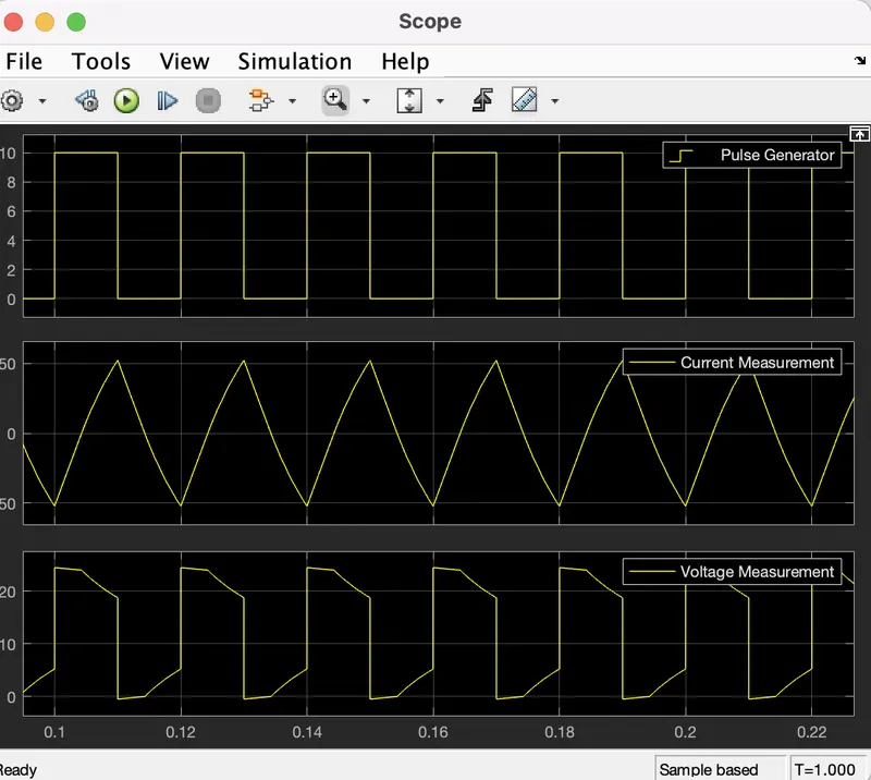
Conclusion: From the graph, voltage is always positive whereas current may be positive or negative. Hence it can be used for motoring and regenerative braking.
3. Explain in a brief about operation of BLDC motor.
Motor: motor is an electrical machine that converts electrical energy into mechanical energy.
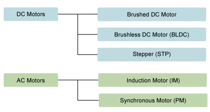
Motor are classified as Dc motors and AC motor. Further it can be classified as follows.
BLDC- Brushless DC motor:
- Brushless DC motor are generated by virtually inverting the stator and rotor of the permanant magnet DC motor.
- It has no brushes and commutators
- Rotation of the rotor depend on the position of the stator
Working principle of BLDC:
- since there is no commutator,the current direction of the conductor in stator is controlled by electronically.
- Rotor is made up of permanent magnet, whereas stator consist of number of windings. when current passes through the stator winding, produce magnetic field and magnetic force.
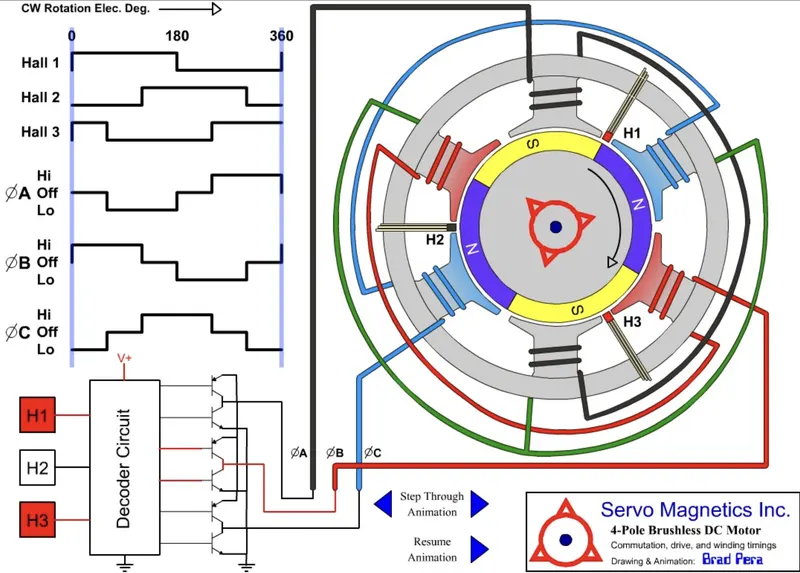
- External commutation circuit is used to rotate the rotor. rotor position is very important.HALL sensor senses the coil position accurately.
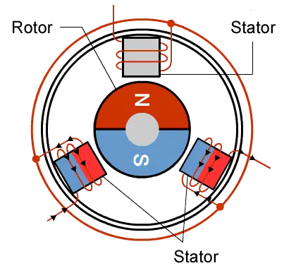
- When electric current passes through a coil in a magnetic field, the magnetic force produces a torque which turns the motor.
- Force in Motor:
F=ILB
F = Force
B = Magnetic Field
L = Length of Conductor
I = Current in Conductor
- Torque in Motor:
T = IBA sin θ
A = LW
L = Length of Winding
W = Width of Winding
- Halls Sensors sense the position of the coils. The Decoder Circuit turns switches on and off.The voltage through the specific coils turns the motor.
Advantages of BLDC:
- Less electrical noise.
- High speed can be achieved.
- As there is no brushes, there is no need for servicing.
- It is computer control so it is more precise.
Disadvantages of BLDC:
- Complex driver circuitary.
- Requires additional sensor.
- It is vey expensive.
Conclusion: Operation of BLDC motor is discussed and have seen the advantages and disadvantages.