Week - 4
1.Implement control logic of a “washing machine” using Stateflow as per given sequence:
- If the power supply is available, the system gets activated
- If the Water supply is not available, stop the process & indicate through LED
- Soaking time should be 200s followed by Washing time of 100s.
- Then rinsing happens for next 20s & dryer runs for 50s
stateflow for washing machine is going to be implemented by using the conditions given above.
(i) if power supply is available, the system will be active
First condition is written in the stateflow form as follows
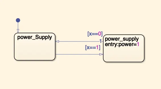
if the supply is 1,then it move on to the next block. if not it get back to inital condition/ system is not activated.
(ii) If water supply is there, then it stop the process and it will be indicated through L
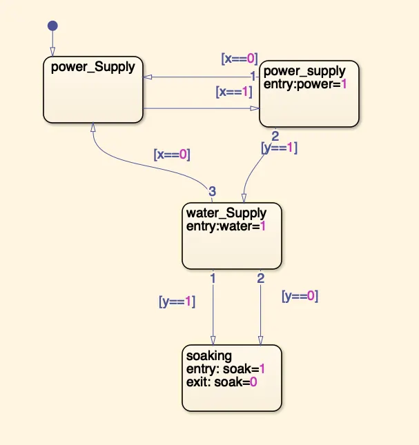
water supply is there,the system will move into the next state "soaking" and LED will glow in green colour. if water supply is not there, then the system wont move to next state that it will be indicated as red light in our washing machine.
(iii)Soaking time should be 200s followed by Washing time of 100s. Then rinsing happens for next 20s & dryer runs for 50s
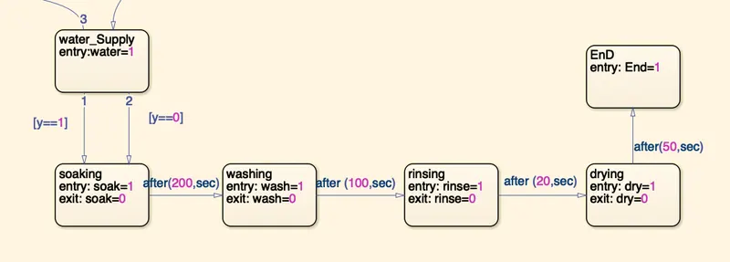
the next conditions such as soaking, washing, rinsing, drying and End are scheduled according to its run time that has been shown above.
Overall stateflow of washing machine for the given condition is
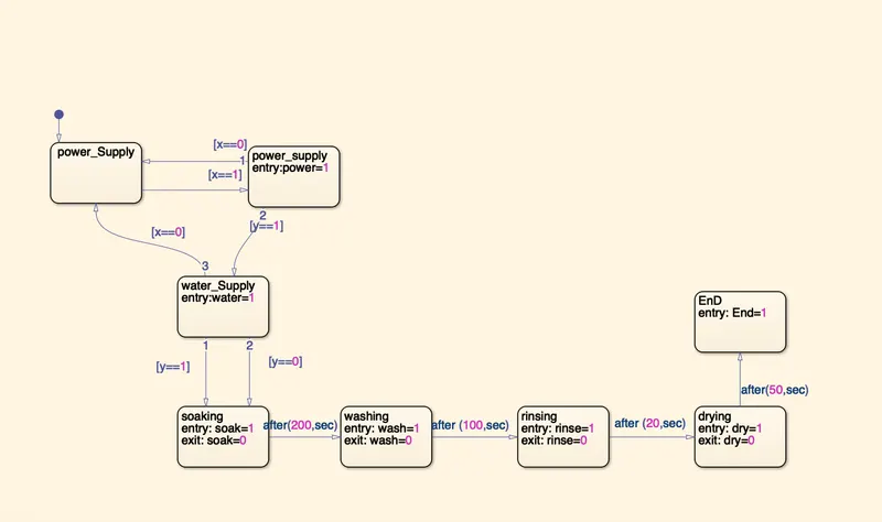
overall washing machine simulink model is
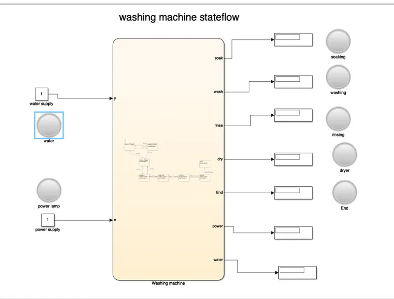
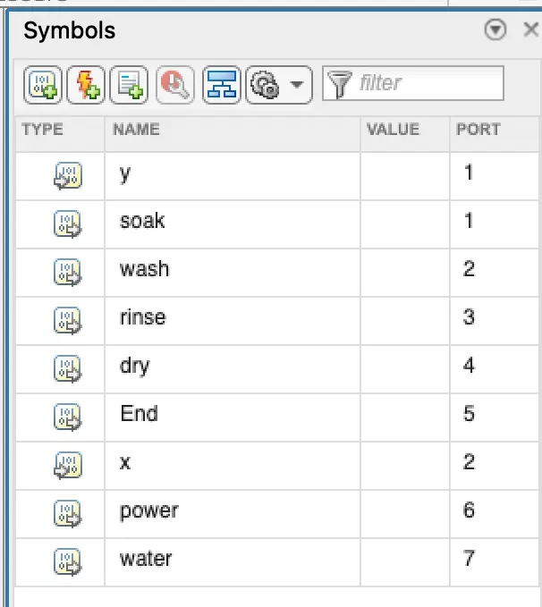
The above module has two inputs such as power supply and water supply. It has five outputs such as soaking,wash,rinse,dry and End. input and output as connected with display and LeD. Here LED is used to understand which state is running at the time of notification. Symbols are ported as below,
now Let us run our model and observe its working
here the power supply is given and LED glows as green
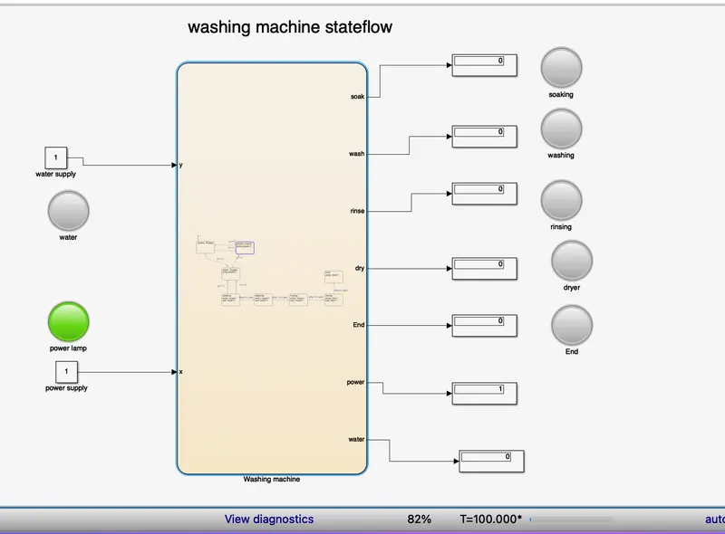
Next stage it check whether water supply is there or not. if water supply is there, then the module will be
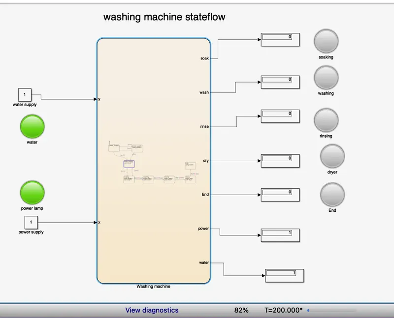
If suppose, the water supply is not there, then the LED will indicate as red colour.
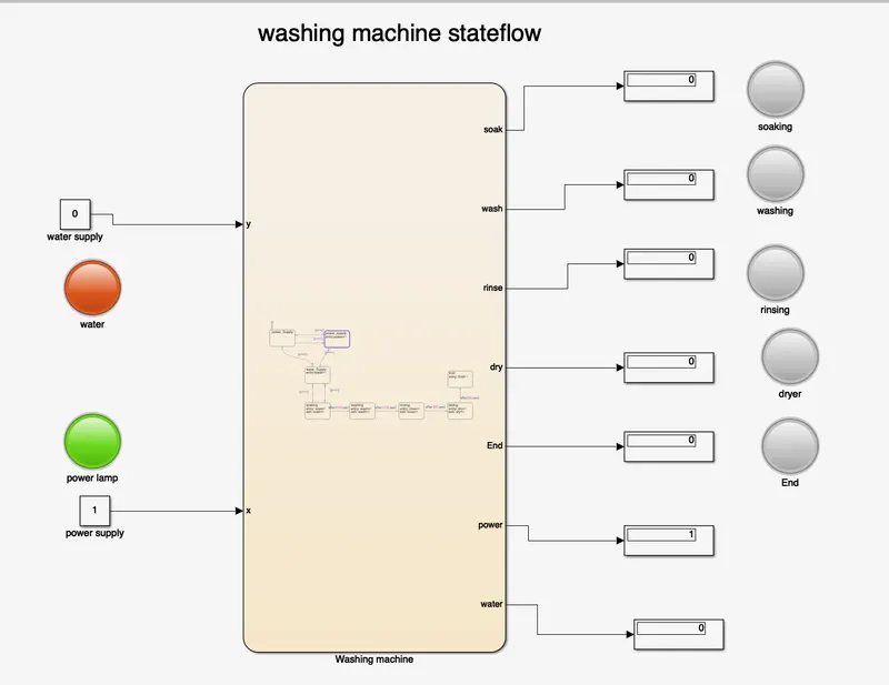
If power is on and water supply is also there, then the washing machine will execute the state as soaking, washing, rinsing, drying and end.
Soaking:
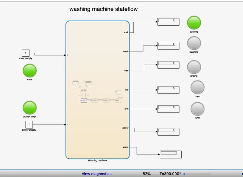
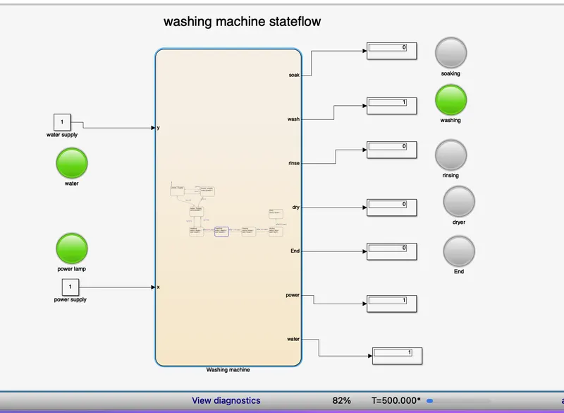
Washing:
Rinsing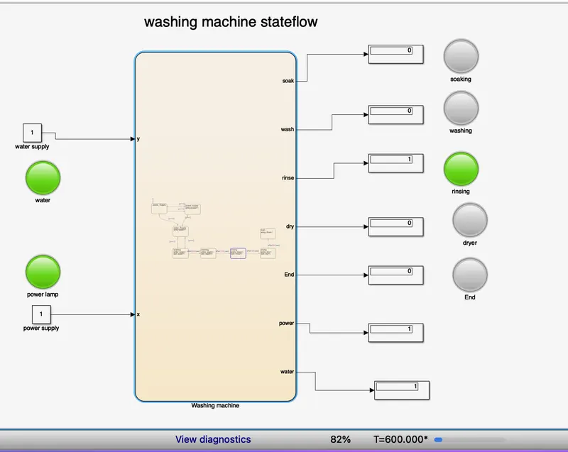
Drying
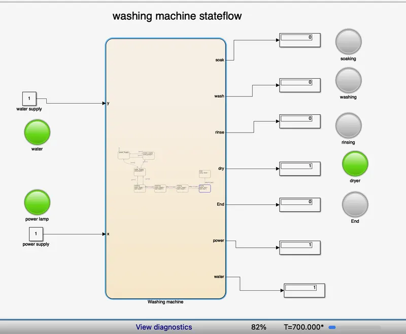
End
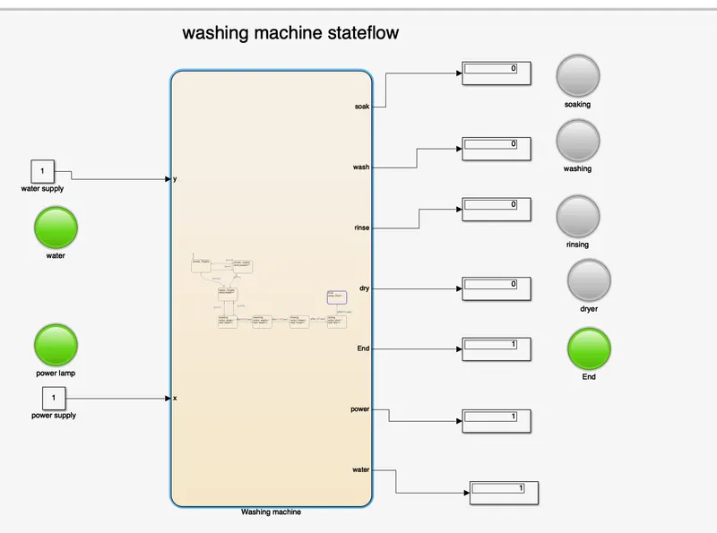
This is how the washing machine works under the given condition. After finishing its function it displays end LED green.
2. Make a Simulink chart for the “Gear shift” logic as per below conditions:
Speed Range(kmph) Gear
0 to 15 1
16 to 25 2
26 to 40 3
41 to 60 4
Above 61 5
Give speed input while the simulation is running & display the gear number.
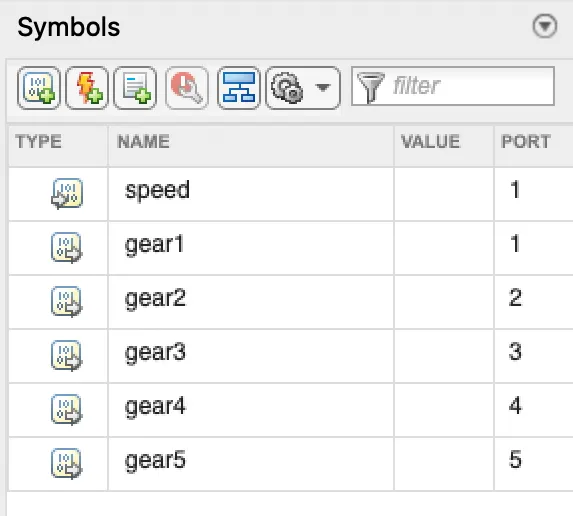
Gear Shift logic is designed using simulink and stateflow. Before moving into the design, just have an idea about the input and output. For the design, one input is required which is speed of the engine. Here purpose of the output is to define the engine is running in which gear.
BY using the speed range and gear, the stateflow of the gear shift is designed as below
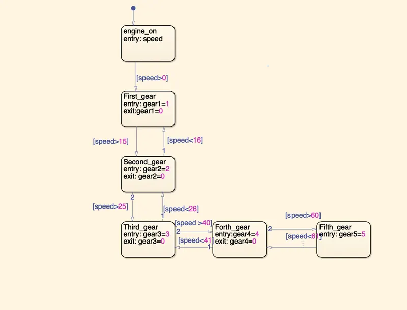
Its output and input parameters are ported as follows
The overall simulink model of the gear shift is
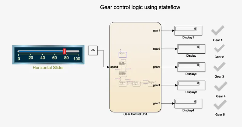
blocks used in design is
constant block by using which speed is given as input.
Horizontal slider block used to vary the speed of the system that is connect with the constant block
Display is generally used to display the outpuy. Here we used to indentify vehicle running in which gear.
Lamp is used to indicate which gear is running. It is purely for the understanding purpose.
Let us start the working of gear control logic,
At initial stage our model will be like the above image.
If the speed is between 0 to 15 Km/Hr, then the control logic execute gear 1 state which is given below,
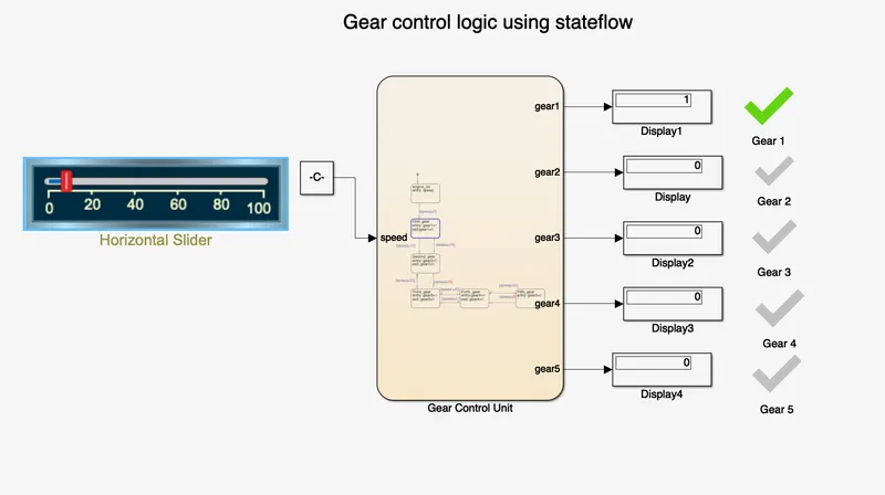
In next case, speed is taken between 16 to 25, hence 2nd gear will be active
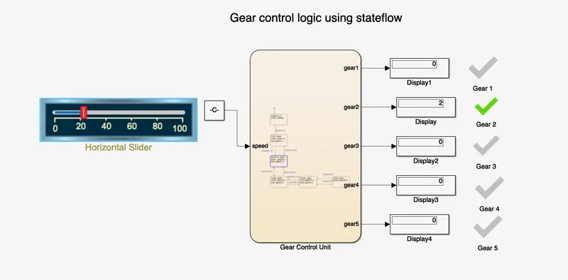
Next case is that speed between 26 to 40, 3rd will be active
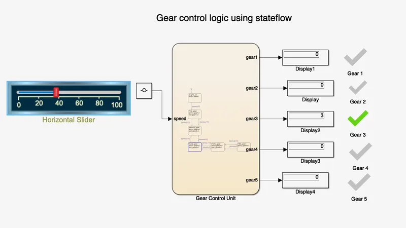
If the speed is between 41 to 69, then gear will be shifted to 4th gear
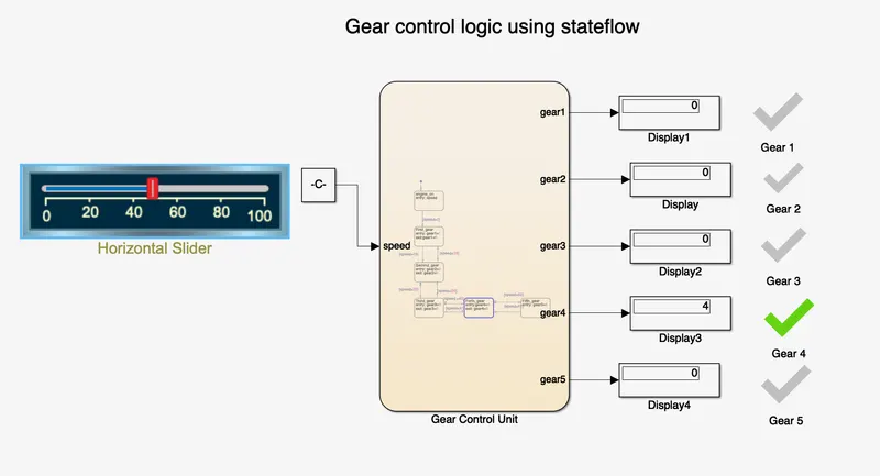
Speed exceed 61km/hr, then gear 5th will be active,
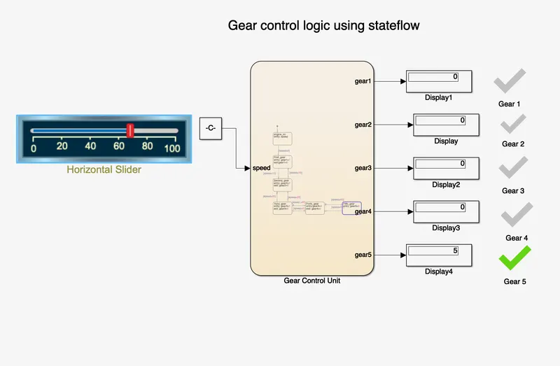
Henceforth, the gear shift model has been designed for th given condition and its working was explained.