Week -2
1.Simulink model for doorbell using solenoid block:
General working principle of doorbell
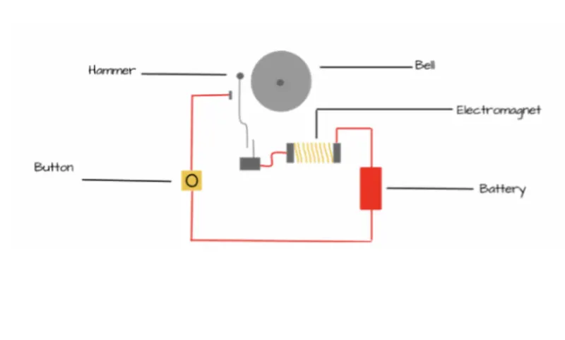
The above diagram shows the doorbell working principle. The electromagnetic coil is connected to the battery. When the switch is on, the electromagnet is produced in the coil which will attract the hammer and pulling of hammer towards the bell causing the bell to ring.
Our design of doorbell with solenoid:
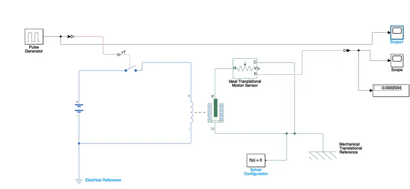
Blocks needed to design the doorbell with solenoid in simulink
- pulse generator: it is used to generate sine,square, triangular waves. In this model we design thr pulse by doing following changes in pulse generator parameter.
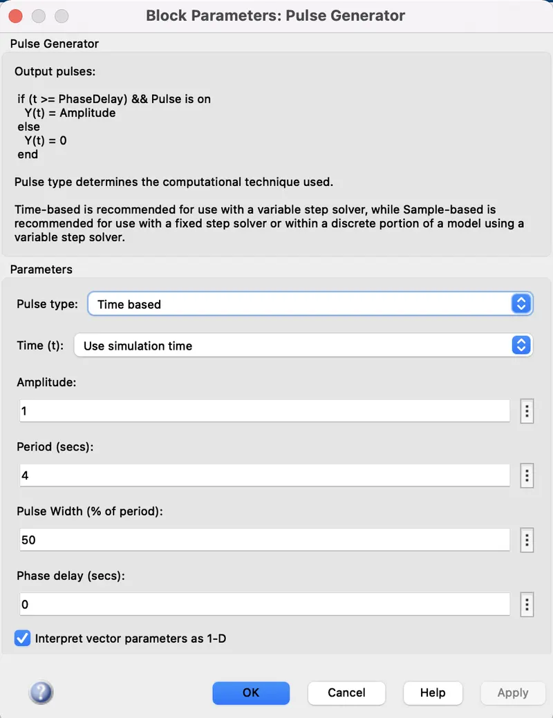
- switch: physical system is controlled by switch
- solenoid: it is an electromagnet. when current pass through it, it produce magnetic force which is used to attract the electromagnetic material.

- ideal translational motion sensor: used to produce control signal with respect to velocity/position.
- solver configuration:it is used to define the solver parameters before the run.
- electrical reference: denotes electrical ground
- Mechanical translational reference: denotes mechanical reference/ground
- Display& Scope: both the blocks used to observe the result of our simulation.
The overall simulink model of doorbell using solenoid for the given condition[where the switch is closed for 2sec and released].
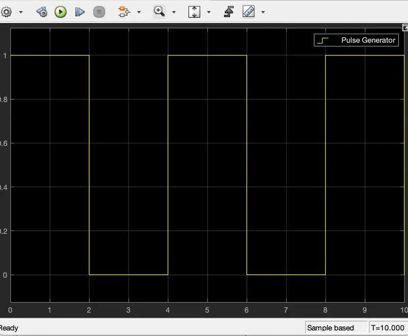
Output of the Pulse generator/ input of the solenoid:
Output of the doorbell using solenoid simulink model:
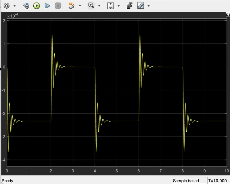
Hence the simulink model for doorbell with solenoid is designed and the output is discussed.
2 Use a thermistor to sense the temperature of a heater & turn on or turn off the fan as per the below conditions:
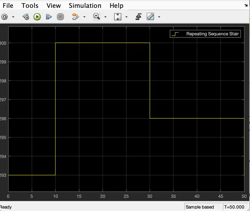
Temperature source: 20 °C from 0 to 10 seconds, 27 °C from 10 to 30 seconds, 23 °C from 30 to 50 seconds
Fan conditions: ON if the temperature above 25 °C, OFF otherwise
Thermistor: it is a type of resistor which is soley depend on the temperature.
simulink design for the given condition is shown below:
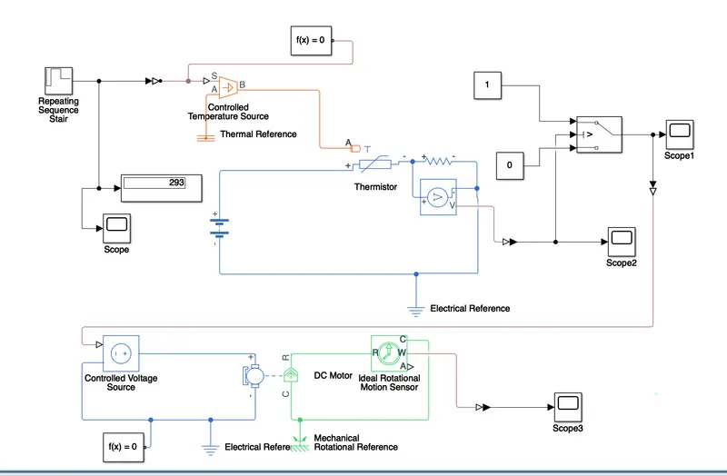
The main blocks used for the simulink thermistor design are
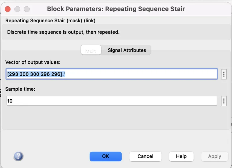
- Repeating sequence stair: this block is used to design the waveform according to our condition. block parameters are assigned as follows,
here the input waveform according to the condition is derived as follows,
- Controlled temperature source: the main purpose of this block is to maintain the temperature regardless of heat flow obsereved by the system. The output of the this block is given as an input to the thermistor.
- Thermistor: it is a type of semiconductor which is intermediant of insulator and conductor.
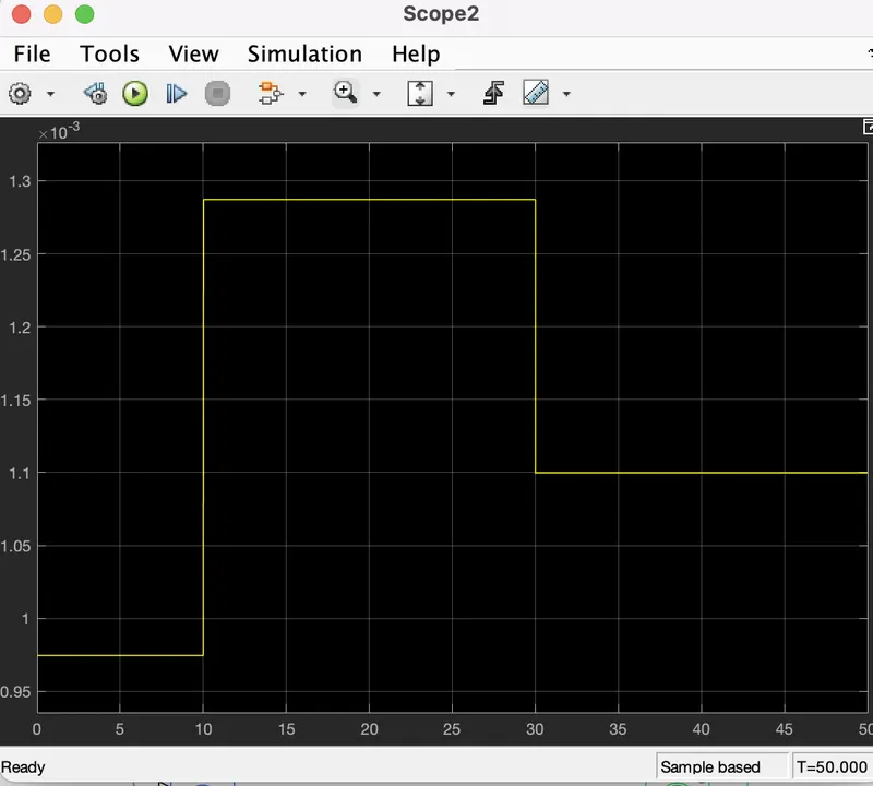
- Voltage sensor: this block is used to sense the voltage output of the thermistor which is followed by the scope display to refer the voltage of the thermistor which is shown below,
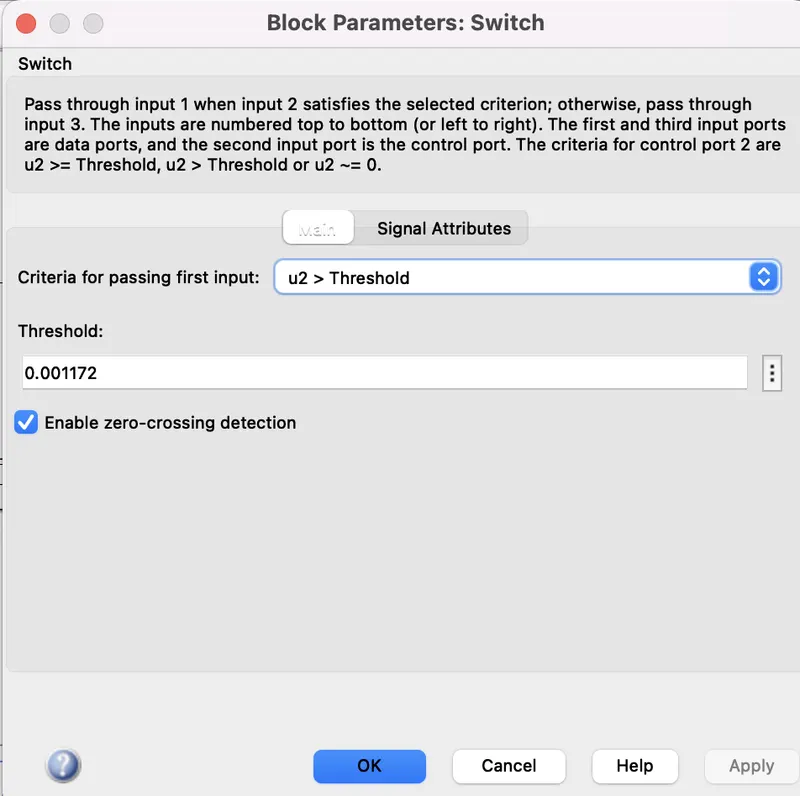
- Switch: used to on the system only at the condition where temperature is greater than 25deg.cel. In the switch the threshold value is set according to the voltage output of the thermistor.
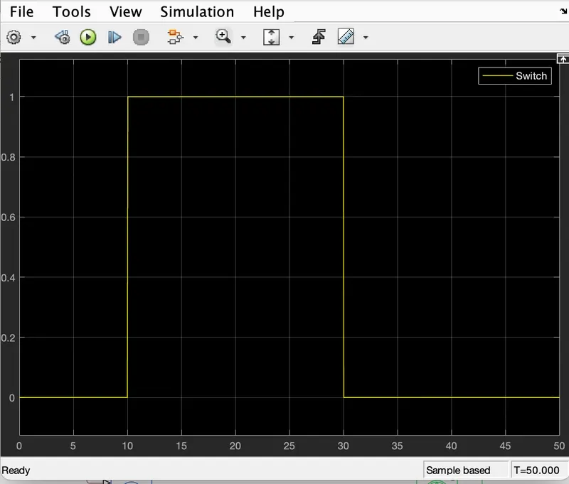
- The working condition of switch is again visulaized with one more scope display and the output is given below
- Fan circuit: it is designed with the blocks such as controlled voltage source, Dc motor and ideal rotational motion sensor. controlled voltage source take the input value from the switch output and the output of voltage source is connected to the Dc motor and by using ideal rotational motion sensor the on and off state of fan is observed. Scope block is used to find the output of the fan circuit and its output is displayed here.
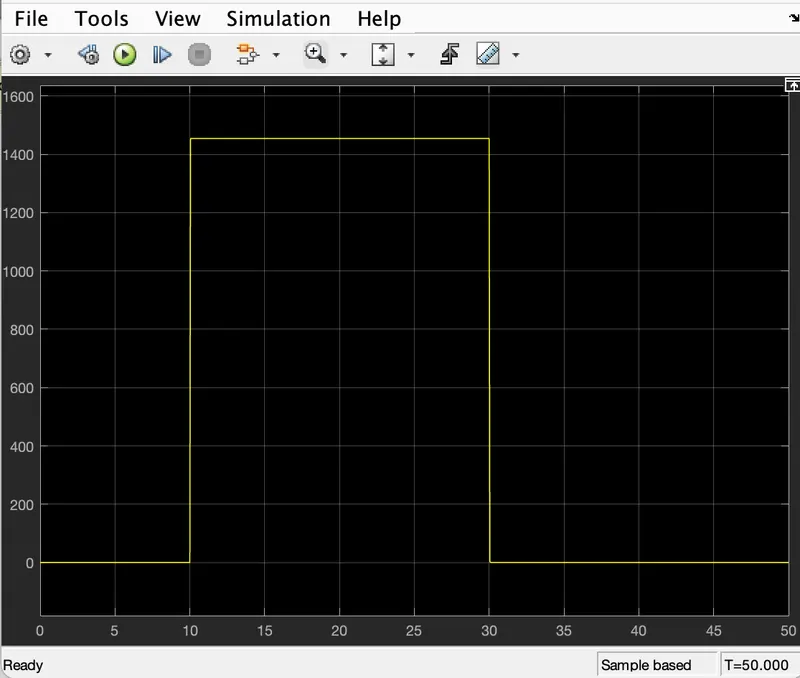
hence from the above figure it is clear that fan is On during the time period of 10 sec to 30 sec because during 10 to 30 sec only the temperature is above 25deg.cel. During remaining rime slot the temperature is below 25deg.cel.