DC Motor Control
AIM
Understanding DC motor control in EV & HEV
OBJECTIVE-1`to Run MATLAB demo ‘Speed control of a DC motor using BJT H-bridge’. Modify the model such that armature current doesn’t shoot up when motor changes direction from forward to reverse.
OBJECTIVE-2`to`Refer to help section of ‘The Four-Quadrant Chopper DC Drive (DC7) block’. Compare it with H-bridge model.
OBJECTIVE-3`to`Make a suitable EV model using DC7 block and make result report.
Note - The sections POINTS TO UNDERSTAND, PRE- REQUISITES, THEORY are for reference purpose. The objectives are answered beyond that.
POINTS TO UNDERSTAND
- Excitation - The excitation is the process of inducing the magnetic field on the parts of the motor with the help of an electric current.
- Cycle - When the alternating quantity goes from through a complete set of +ve or –ve value or goes through 360° electrical degrees, then it is said to have completed a cycle completely.
- Frequency - is the number of times a sine wave repeats, or completes, a positive-to-negative cycle.
- Phase - The phase of an alternating quantity is defined as the divisional part of a cycle through which the quantity moves forward from a selected origin. When the two quantities have the same frequency, and their maximum and minimum point achieve at the same point, then the quantities are said to have in the same phase.
- Single Phase Supply - The single phase requires two wires for completing the circuit, i.e., the conductor and the neutral. The conductor carries the current and the neutral is the return path of the current. The single phase supplies the voltage up to 230 volts. It is mostly used for running the small appliances like a fan, cooler, grinder, heater, etc.
-
Polyphase system - can be a two-phase system, three-phase system or six-phase system. But mainly the three-phase system is used for all practical purposes. It is a combination of two or more than two voltages having same magnitude and frequency but displaced from each other by an equal electrical angle. As poly means, many (more than one) and phase means windings or circuits. Each of them has a single alternating voltage of the same magnitude and frequency. So, whenever the term Polyphase is used, it means a Three Phase System unless it is mentioned otherwise.
- Three-Phase System - The three phase system consist four wires, three conductors and one neutral. The conductors are out of phase and space 120º apart from each other. The three phase system is also used as a single phase system. For the low load, one phase and neutral can be taken from the three phase supply.
| Basis For Comparison | Single Phase | Three Phase |
|---|---|---|
| Definition | The power supply through one conductor. | The power supply through three conductors. |
| Wave Shape |  |
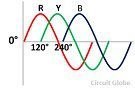 |
| Number of wire. | Require two wires for completing the circuit. | Requires four wires for completing the circuit. |
| Voltage | Carry 230V | Carry 415V |
| Phase Name | Split phase | No other name |
| Power Transfer Capability | Minimum | Maximum |
| Network | Simple | Complicated |
| Power Failure | Occurs | Do not occur |
| Loss | Maximum | Minimum |
| Power Supply Connection | 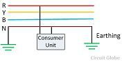 |
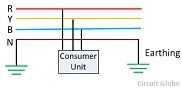 |
| Efficiency | Less | High |
| Economical | Less | More |
| Uses | For home appliances. | In large industries and for running heavy loads. |
- Rotating Magnetic Field - The field having moving polarities is known as the rotating magnetic field. The rotating magnetic field develops only in the polyphase system. Because of the rotating magnetic field, the north and south poles develop on the stator.
- The armature winding is the main winding because of which the EMF induces in the motor.
- Salient Pole - The word salient means the poles of the rotor projected towards the armature windings.
- Synchronous speed - is the constant speed of the machine whose value depends on the frequency and the numbers of the pole of the machine.
- Single excited motor - the supply is applied only to the one part, i.e. either stator or rotor, not both.
- Short-Circuit - The circuit that allows the electric current to pass through the random path which has low resistance is known as the short circuit. The short circuit causes the heavy current which damages the insulation of the electrical equipment. It mainly occurs when the two wire touches each other or when the insulation between the conductor breaks down.
- p–n junction - is a boundary or interface between two types of semiconductor materials, p-type and n-type, inside a single crystal of semiconductor. The "p" (positive) side contains an excess of holes, while the "n" (negative) side contains an excess of electrons in the outer shells of the electrically neutral atoms there. This allows electrical current to pass through the junction only in one direction. The p-n junction is created by doping.
- Bias - is the application of a voltage across a p–n junction.
- Forward Bias - is in the direction of easy current flow.
- Reverse bias - is in the direction of little or no current flow. The forward-bias and the reverse-bias properties of the p–n junction imply that it can be used as a diode.
- Snubber circuit - limits or stops (snubs) switching voltage amplitude and its rate of rise, therefore reducing power dissipation. In its simplest form, a snubber circuit basically consists of a resistor (R) and capacitor(C) connected across the transistor.
- Diode - A diode is a semiconductor device composed of P and N-type semiconductor material. It conducts under forward biased condition when the applied potential exceeds the barrier potential. Thus acts as a closed switch. While under reverse biased condition, the diode stops conducting and functions as an open switch.
- Freewheeling (Flyback) diode - operates in the same way that it conducts in forward biased condition but do not conducts in reverse biased condition.
PRE- REQUISITES
DC Machines - The use of DC is very much limited since the power supply is usaually available in AC only.They are still used in traction, cranes, ev etc. Two types of DC macines- DC Generator and DC Motor.
DC motor - DC machine which converts electrical energy into mechanical energy. DC motors works on the principle that when a current carrying conductor is placed in a magnetic field, the conductor experiences a mechanical force.
DC Generator - DC machine which converts mechanical energy into electrical energy. They work on the principle of electromagnetic induction. According to Faraday's law of electromagnetic induction, whenever a conductor cuts magnetic lines of flux, a dynamic emf is induced in the conductor. This emf causes a current flow if the circuit is closed.
When purchasing a motor, it’s often asked which technology is better, AC or DC, but the fact is that it is application and cost dependent. Here we will focus on motor.
DC Motors -
DC motors were the first type of motor widely used and the systems (motors and drive) initial costs tend to be typically less than AC systems for low power units, but with higher power the overall maintenance costs increase and would need to be taken into consideration. The DC Motors speed can be controlled by varying the supply voltage and are available in a wide range of voltages, however the most popular type are 12 & 24V, with some of the advantages being:
`to`Easy installation
`to`Speed control over a wide range
`to`Quick Starting, Stopping, Reversing and Acceleration
`to`High Starting Torque
`to`Linear speed-torque curve
DC motors are widely used and can be used from small tools and appliances, through to electric vehicles, lifts & hoists
Types of DC Motors -
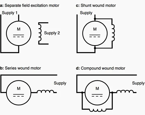
| Types of DC Motor | Characteristics | Applications |
| DC Shunt Motor |
|
For driving constant speed, line shafting lathes, Centrifugal pumps, Machine tools, Blowers and Fans, Reciprocating pumps |
| DC Series Motor |
|
Traction motors, electric locomotives, trolly cars, cranes and hoist conveyors |
| Cummulative Compound DC Motor |
|
Punches and shears, elevators and conveyors, rolling mills, air compressors, heavy planers |
When an external dc supply is connected to the motor terminals the field magnets are excited, developing alternate north an dsouth polarities. Armature conductors under N-pole carry currents in one direction while those under S-pole carry currents in the opposite direction. For the direction of currents in the conductors, the force on each conductor tends to rotate the armature in anti-clockwise direction. All these forces add together to produce a driving torque which results in the rotation of armature.
Back EMF or Counter EMF - When the armature of dc motor rotates in amagnetic field, the armaturse conductors cut the magnetic flux. According to the Faraday's Law electromagnetic inductio, an emf is induced in the conductors. Thee induced emf acts in opposite direction to the applied voltage as per Lwnz's law and is known as back emf or counterenf. It is less than applied voltage. The back emf induced is given by `E_b=(phiZN)/60*P/A`. Due to back emf the armature takes more current from the supply when it is loaded. So armature current automaticallly changes with the increase of the load on the motor. If there is no back emf the armature may take very high current and winding may be damaged. At the time of starting there is no back emf and therefore the motor takes high current. To avoid this high current starters are used with the motor for its safety.
AC Motor -
AC motors are highly flexible in many features including speed control (VSD - Variable Speed Drive) and have a much larger installed base compared to DC motors, some of the key advantages are:
`to`Low power demand on start
`to`Controlled acceleration
`to`Adjustable operational speed
`to`Controlled starting current
`to`Adjustable torque limit
`to`Reduced power line disturbances
The current trend for VSD is to add more features and programmable logic control (PLC) functionality, which are advantages for the experienced used, but require greater technical expertise during maintenance.
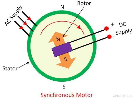
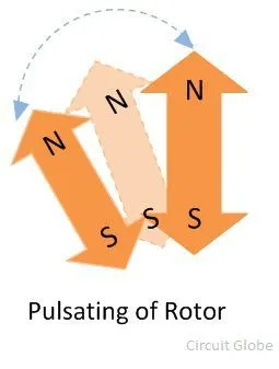
Synchronous AC Motor - The motor which runs at synchronous speed (i.e.constant speed at which motor generates the electromotive force) is known as the synchronous motor. The synchronous motor uses the salient pole rotor. Th rotor is given the dc supply and the stator is given the 3-phase supply. The DC supply being constant induces N and S poles, hence, fixed flux and polarity. And AC being sinusoidal, polarity of the wave changes in every half cycle. When the rotor and stator have the same polarity repels, otherwise, attracts. The rotor attracts the stator in the 1st half cycle and pulsates in the 2nd half cycle. This is the reason because of which the synchronous motor is not self-starting. Hence a prime mover is used to rotate the rotor initially, and when the synchronous speed is achieved, prime mover is disconnected. The north and south poles of the rotor and the stator interlock each other. Thus, the rotor starts rotating at the speed of the rotating magnetic field. And the motor runs at the synchronous speed. The speed of the motor can only be changed by changing the frequency of the supply.
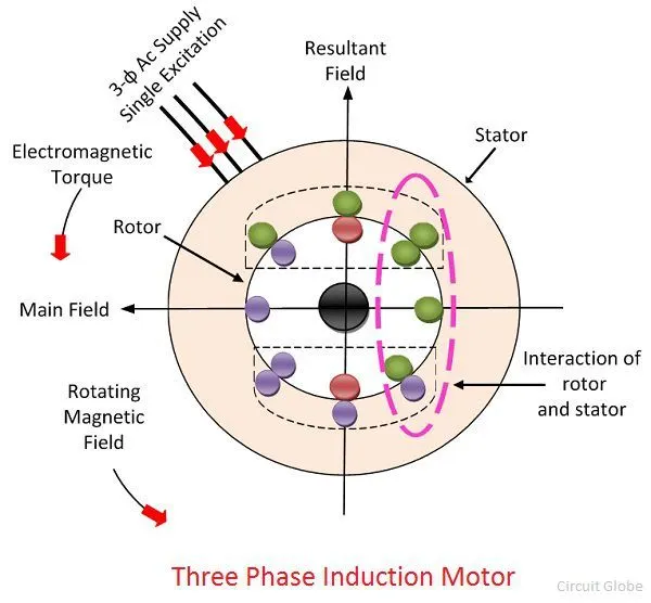
Asynchronous AC (Induction) Motor - The stator and rotor are two essential parts of the motor and the windings of the stator are equally displaced from each other by an angle of 120°. This motor is single excited with the stator by applying 3-phase supply, and the rotor is not given any excitation. Hence a rotating magnetic field is produced in stator. The stationary winding in the rotor cuts the rotating magnetic field. This causes an EMF induced in the rotor windings because of electromagnetic induction. The relative motion between the rotating magnetic field and the rotor windings induces the current in the rotor windings. To make this current large, the conductors of the rotor are short-circuited either by the end rings or by the help of the external resistance. As the current flows through the windings, the flux induces on it. The direction of rotor flux is same as that of the rotor current. Now we have two magnetic fields, one due to rotating magnetic field in the stator and the other due to rotor windings. These fluxes interact each other. On one end of the conductor the fluxes cancel each other, and on the other end, the density of the flux is very high. Thus, the high-density flux tries to push the conductor of rotor towards the low-density flux region. This phenomenon induces the torque on the conductor, and this torque is known as the electromagnetic torque.
The speed of the rotor is always less than the rotating magnetic field or synchronous speed. The rotor tries to the run at the speed of the rotor, but it always slips away. Thus, the motor never runs at the speed of the rotating magnetic field, and this is the reason because of which the induction motor is also known as the asynchronous motor.
Why rotor never runs at synchronous speed? If the speed of the rotor is equal to the synchronous speed, no relative motion occurs between the rotating magnetic field of the stator and the conductors of the rotor. Thus the EMF is not induced on the conductor, and zero current develops on it. Without current, the torque is also not produced.
THEORY
What is a motor drive? The system which is used for controlling the motion of an electrical machine, such type of system is called an electrical drive. In other words, the drive which uses the electric motor is called electrical drive. The electrical drive uses any of the prime movers like diesel or a petrol engine, gas or steam turbines, steam engines, hydraulic motors and electrical motors as a primary source of
energy. This prime mover supplies the mechanical energy to the drive for motion control.
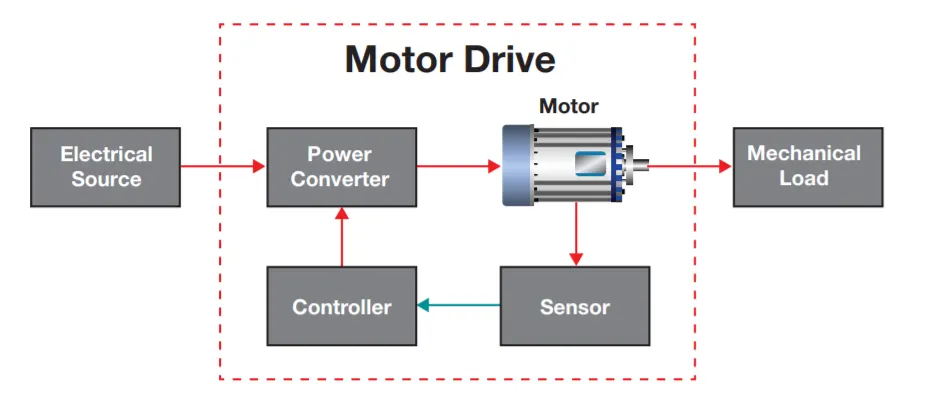
Parts of a Electric Drive - The main parts of the electrical drives are power converter, motor, controller and sensing units. They are:-
`to`Power Converter - The power modulator regulates the output power of the source. It controls the power from the source to the motor in such a manner that motor transmits the speed-torque characteristic required by the load. During the transient operations like starting, braking and speed reversing the excessive current drawn from the source. This excessive current drawn from the source may overload it or may cause a voltage drop. Hence the power modulator restricts the source and motor current.
The power modulator converts the energy according to the requirement of the motor e.g. if the source is DC and an induction motor is used then power modulator convert DC into AC. It also selects the mode of operation of the motor, i.e., motoring or braking.
`to`Controller - The control unit controls the power modulator which operates at small voltage and power levels. The control unit also operates the power modulator as desired. It also generates the commands for the protection of power modulator and motor. An input command signal which adjusts the operating point of the drive, from an input to the control unit.
`to`Sensor - It senses the certain drive parameter like motor current and speed. It mainly required either for protection or for closed loop operation.
Power Electronics - refers to the process of controlling the flow of current and voltage and converting it to a form that is suitable for user loads. A power electronic system converts electrical energy from one form to another and ensures Maximum efficiency & reliability, availability, Minimum cost, Least weight, Small size. Applications of Power Electronics are classified into two types −
`to`Static Applications - This utilizes moving and/or rotating mechanical parts such as welding, heating, cooling, and electro-plating and DC power.
`to`Drive Applications - Drive applications have rotating parts such as motors. Examples include compressors, pumps, conveyer belts and air conditioning systems.
Why we need Power Electronics? The majority of the technologies of modern days are mostly user friendly and more importanly pocket-friendly. The gadgets of today are smaller size and devoid of having any moving parts. Hence the circuit switching mechanisms cannot have mechanical switchings causing huge amount f losses and that too with fast open-off trigger. Hence power electronics is the most suitable and viable options to opt for.
What are switching devices in power electronics? Power electronic switching device is a combination of active switchable power semiconductor drivers which are integrated into one. Major distinctiveness of the switch will be determined by the inner association of functions and interactions of its integrated system. As a result, main striking feature in a power electronic switch is the capability of dissipating low or almost no power. Consequently, electronic switch can achieve a low and continuous surge of power.
Electronic components in power electronics -
`to`Linear Circuit Elements - the components of an electrical circuit which shows a linear relationship among the current input and voltage output. They are resistors, capacitors, inductors and transformers.
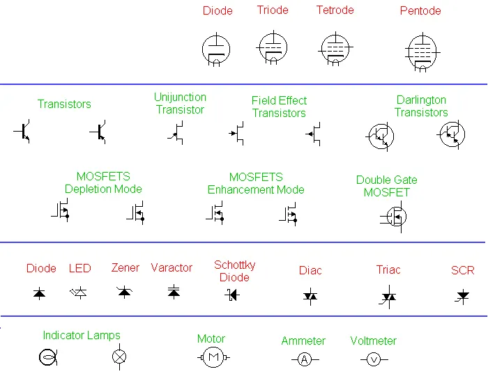
`to`Switching Devices - Diode, SCR (Silicon Controlled Rectifiers), BJT (Bipolar Junction Transistor), IGBT(Insulated Gate Bipolar Transistor), MOSFET (Metal Oxide Semiconductor Field Effect Transistor), TRIAC (Triode for Alternating Current)
OBJECTIVE-1`to Run MATLAB demo ‘Speed control of a DC motor using BJT H-bridge’. Modify the model such that armature current doesn’t shoot up when motor changes direction from forward to reverse.
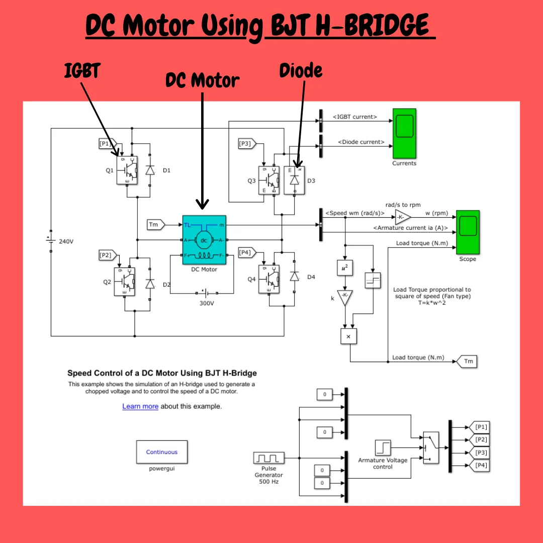
The above said SIMULINK model is opened in MATLAB by typing "power_Hbridge" in the command window.
Blocks Used
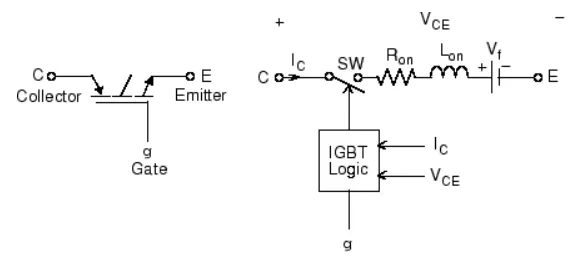
`to`IGBT - The IGBT block implements a semiconductor device controllable by the gate signal. The IGBT is simulated as a series combination of a resistor Ron, inductor Lon, and a DC voltage source Vf in series with a switch controlled by a logical signal (g > 0 or g = 0). The IGBT block contains a series Rs-Cs snubber circuit, which is connected in parallel with the IGBT device (between terminals C and E).
When `V_(CE)>0, V_(CE)>V_f, g>0``to`ON state
When `V_(CE)>0, g=0``to` OFF state
Why IGBT is used when the model is to control DC Motor using BJT? The Bipolar Junction Transistor (BJT) when used for power switching applications, operates as an IGBT. When it is conducting (BJT operating in the saturated region), a forward voltage Vf is developed between collector and emitter (in the range of 1 V). Therefore, the IGBT block can be used to model the BJT device.
`to`Diode - The Diode block models a piecewise linear diode. If the voltage across the diode is bigger than the Forward voltage parameter value, then the diode behaves like a linear resistor with low resistance, given by the On resistance parameter value, plus a series voltage source. If the voltage across the diode is less than the forward voltage, then the diode behaves like a linear resistor with low conductance given by the Off conductance parameter value.
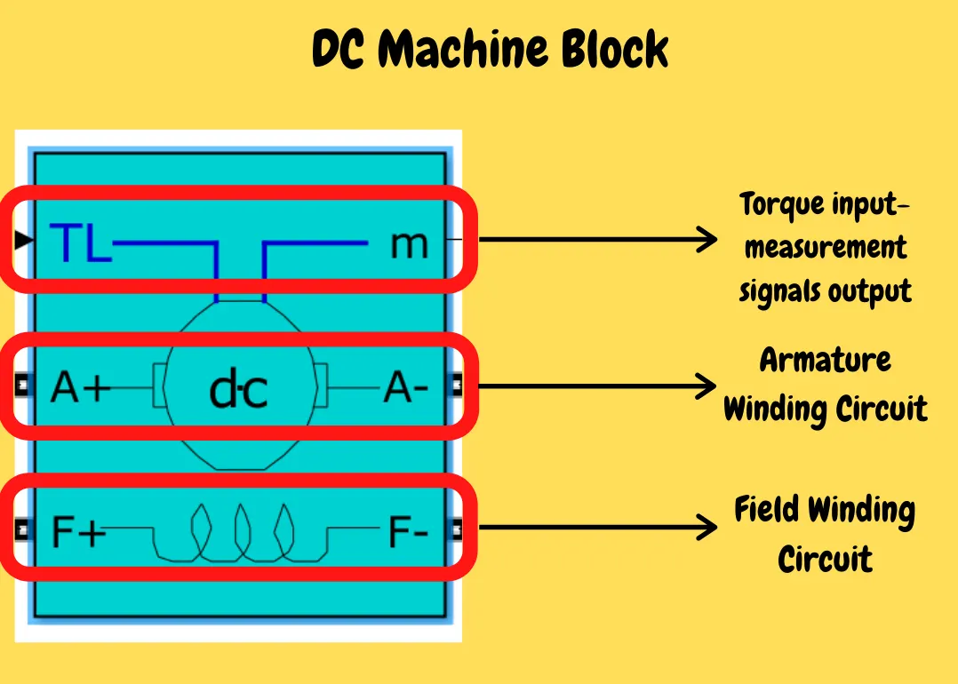
`to`DC Machine - The DC Machine block implements a wound-field or permanent magnet DC machine. This block consists of 3 segments- armature circuit, field circuit and a torque input-measurement signas output. The motor used here is 5HP, 240V, 1750 RPM. It simulates a fan type model, proportional to square of speed. The armature voltage can be varied from 0 to 240V by changing the duty cycle. The duty cycle can be changed by pulse width generator block.
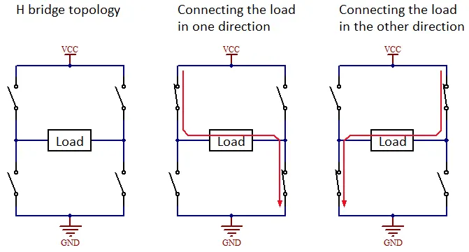
Here the Dc Machine is used as DC motor. We need to control the DC motor's rotation in such a way that when to spin ACW & when to spin CW and with variable speeds. For that we use a H-bridge configuaration of circuits. The name H-bridge is given as the circuit resembles the letter "H".
This circuit requires switches that can automatically turn ON/OFF very fastly as per the requirements. Hence we use power switches. The switch used is IBJT, but the model is said to have a BJT because BJT works as IGBT as a switch. Refer the picture below -
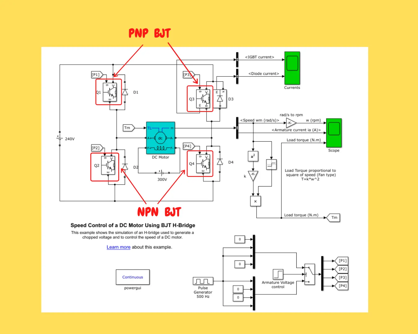
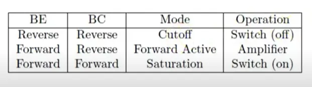
From the above table it is clear that, when the BJT is in saturation or conducting state, the Base-Emitter and Base-Collector is forward bias. Hence the BJT act in ON state. The BJT is controlled by SIMULINK signals as 1 and 0. Note that a logic “1” represents a higher voltage, such as 5 volts, which is commonly referred to as a HIGH value, while a logic “0” represents a low voltage, such as 0 volts or ground, and is commonly referred to as a LOW value. But to make this 5 volts as 1 volt, we have used IGBT block instead of BJT. The H-bridge consists of 4 transistors, namely Q1, Q2, Q3 & Q4. Each one has a snubber circuit connected in parallel.
The H- bridge works in such a way that at a time two IGBT AND 2 Diodes are in on state. When the IGBT's Q2 & Q3 are in conducting state and rhe diodes D1 & D4 act as a freewheeling diodes, makes the motor to spin in a one direction. When the IGBT's Q1 & Q4 are in conducting state and the diodes D2 & D4 act as freewheelig diodes, makes the motor to spin in opposite direction. The motor speed can be controllled by the self-excitation voltage provided across the rotor windings (i.e. 0 to 300V).
when the SIMULINK model is run, the output obtained is as shown -
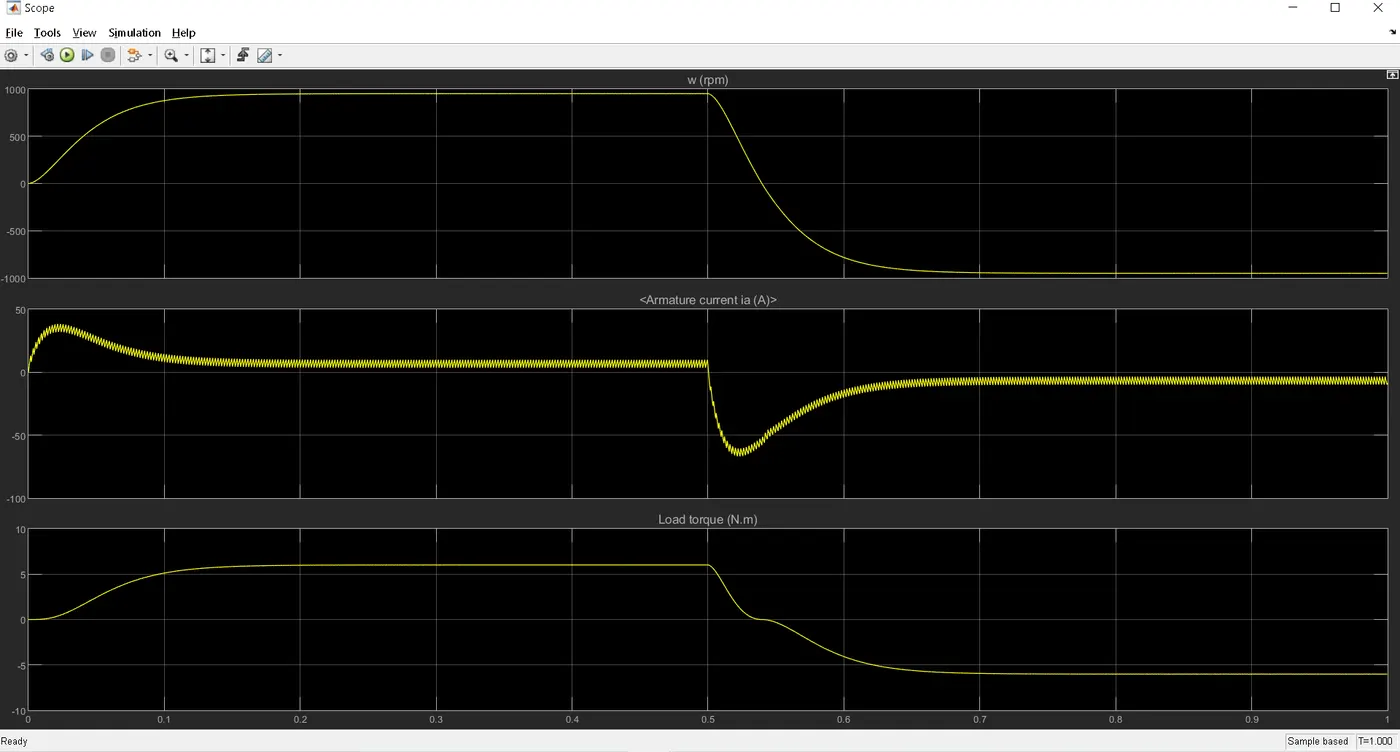
In the above plot, armature current has sudden rise and drop when the motor changes direction from forward to reverse motion.
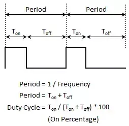
NOTE - A Pulse Width Modulation (PWM) Signal is a method for gnerating analog signal using a digital source and a frequency. By cycling a digital signa OFF and ON at a fast enough rate, and with a certain duty cycle, the output will appear to behave like a constant voltage and current analog signal when providing power to devices.
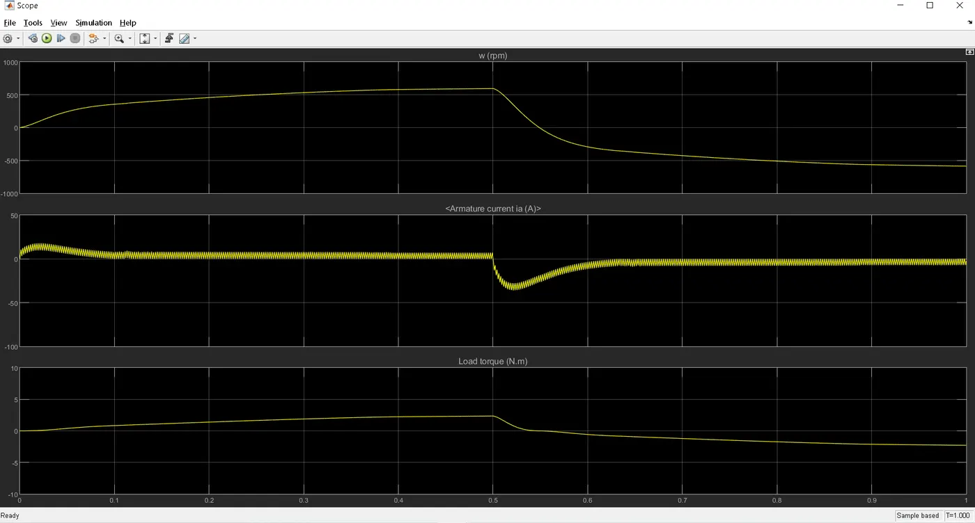
You can see the first plot of speed, starts from positive side then runs constanly at that rpm and then suddenly drops and spin in opposite direction. Simultaneously the armature current also spikes up initiallly at the start and also at the reversal of armature voltage causing the rotor to spin in opposite direction. This happens because by default, the armature voltage control is set at a step time of t=0.5. It means at t=0.5s the motor rotation will change in reverse direction as the armature voltage will reverse.
To minimize the sudden surge in the armature current at the start and when the motor runs in reverse, we have to modify the duty cycle. The default value is 75%. This means that the voltage is supplied 75% of the time to the motor and the rest 25%, the motor receives no voltage from the source and it is in OFF state. This sudden change in OFF and ON state (i.e. reversal of armature voltage) causes the armature current to spike up abruptly.
when the duty cycle is 60% - there is sudden spike of armature current.
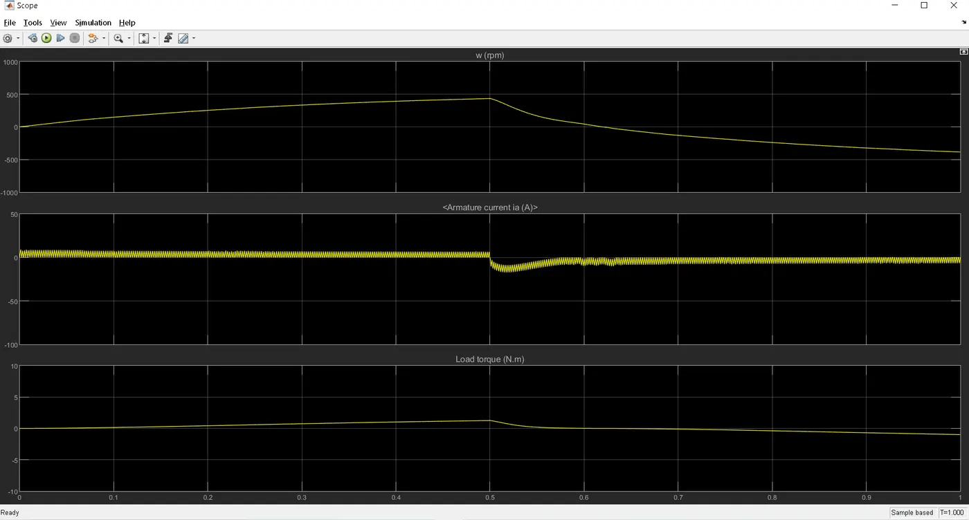
When duty cycle is 50% - there is again sudden spike in armature current when the armature voltage reverses at t=0.5s. But it is not at the start of the motor.
When the duty cyle is 40% - the sudden surge in the armature current at the start of the motor and at t=0.5s has been reuced. And the armature current is constant approximately 7A in the both +ve and
-ve directions.
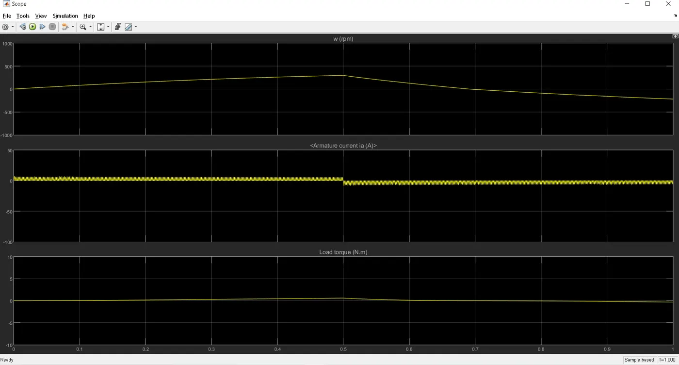
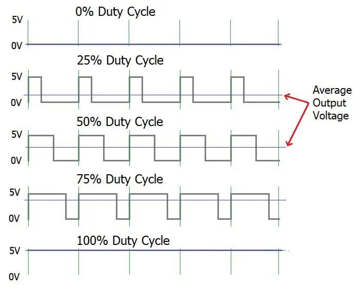
so we can say that the switching devices (i.e. IGBT) has to be turned ON and OFF at a fast rate. For that the PWM switching frequency has to be high enough not to affect the load. The switching device's frequency produced by a duty cycle of 75% will not be high enough to deliver a smooth load waveform. It has to an average value of voltage a shown in the picture below.
REFERENCE
for synchronous AC Motor - https://circuitglobe.com/synchronous-motor.html
for induction motor - https://circuitglobe.com/working-principle-of-an-induction-motor.html
for electric drive - https://www.ti.com/lit/wp/slyy078a/slyy078a.pdf?ts=1602567013767&ref_url=https%253A%252F%252Fwww.google.com%252F
for electric drive - https://circuitglobe.com/electrical-drive.html
for power electronics - https://www.tutorialspoint.com/power_electronics/power_electronics_introduction.htm
https://www.electronicsforu.com/market-verticals/electrical-drives-applications-power-electronics
for diode, freewheeling diode - https://electronicscoach.com/freewheeling-diode.html
for H Bridge - https://www.youtube.com/watch?v=xSnbx5Nzn5E
------------------------------------------------------------------------------------------------------------------------------------------------------------------------------------------------------------------------------------------------------------------------------------------------------------------------------------------------------------------------------------------------------------------------------------------------------------------------------------------------------------------------------------------------------------------------------------------------------------------------------------------------------------------------------------------------------------------------------
OBJECTIVE-2`to`Refer to help section of ‘The Four-Quadrant Chopper DC Drive (DC7) block’. Compare it with H-bridge model.
`to`The model is obtained by typing dc7_example in the command window. The model looks like as shown below -
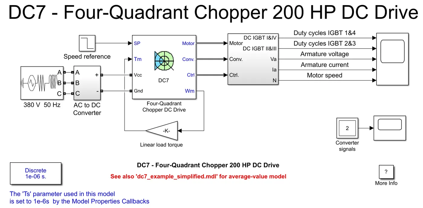
Here the power supply is not dc. It is a 380v 50Hz AC power supply. It means that the rotor of the generator turns 50 cycles per second, the current changes 50 times per second back and forth, direction changes 100 times. That means the 380V changes from positive to negative, and from negative to positive voltage, this process converts 50 times/second.
The model contains AC to DC Converter (i.e Rectifier Bridge + Braking Chopper), Four-Quadrant Chopper DC Drive, bus model subsystem. The applied AC 380V is converted to 515V dc supply by an AC to DC converter. This converter includes a rectifier and a braking chopper. The braking chopper is used to convert the voltage from the motor while regenerative braking, exceeding a threshold voltage into thermal energy. This is done by the brake resistor connected in series with the diode and a switching device inside the braking chopper. The braking chopper activates when the voltage reaches 560V and it switches OFF when voltage is 520V. Though AC source is coverted to 515V, we must include losses. Hence the voltage is kept at 520V.
The motor runs based on the speed reference block provided.
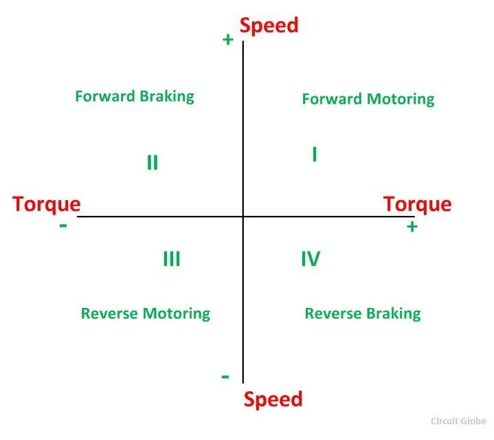
`to`Four quadrant operation of DC Motor - A motor operates in two modes – Motoring and Braking. A motor drive capable of operating in both directions of rotation and of producing both motoring and regeneration is called a Four Quadrant variable speed drive. In motoring mode, the machine works as a motor and converts the electrical energy into mechanical energy, supporting its motion. In braking mode, the machine works as a generator and converts mechanical energy into electrical energy and as a result, it opposes the motion. The Motor can work in both, forward and reverse directions.
| Function | Quadrant | Speed | Torque | Power Output |
|---|---|---|---|---|
| Forward Motoring | I | + | + | + |
| Forward Braking | II | + | - | - |
| Reverse Motoring | III | - | - | + |
| Reverse Braking | IV | - | + | - |
`to`Applications of 4 - Quadrant Operation
- Compressor, pump and fan type load requires operation in the I quadrant only. As their operation is unidirectional, they are called one quadrant drive systems.
- Transportation drives require operation in both directions.
- If regeneration is necessary, application in all four quadrants may be required. If not, then the operation is restricted to quadrants I and III, and thus dynamic braking or mechanical braking may be required.
- In hoist drives, a four-quadrant operation is needed.
The simulink DC7 four quadrant drive contains a speed and current controller, regulator swich, chopper , dc motor
`to`speed controller block - The inputs are speed reference and motor speed, and outputs a current reference. This output current reference is inturn used by the current controller block to obtain the electromagnetic torque needed to reach the desired speed.
`to`Regulation Switch block - The Regulation Switch block consists of a DC machine (wound-field type) torque controller model and a Simulink Switch model. The later is used to select the regulation mode, i.e. torque or speed regulation of the DC drive. The torque controller provides a DC current reference. A second reference DC current is obtained from the speed controller. Depending on the regulation mode, the Simulink switch selects between the two DC current references.
`to`current controller block - The Current Controller (DC) block models a PI current controller for use with a DC machine. The block has multiple instances, depending on the DC drive type (chopper DC drive or thyristor-based DC drive) and operating quadrants (one-, two-, or four-quadrant). It has two operating modes to represent a detailed or an average-value current controller. The inputs of the DC current controller block are the current reference (in pu) and the armature current flowing through the motor. The outputs are current reference, duty cycles, PWM pulses, and reference current error. From here the PWM pulses are fed to the chopper block where the switches are present.
`to`chopper block - The Chopper block models a standard half-bridge (one leg, two IGBTs) or full-bridge (two legs, four IGBTs) converter model. It has two operating modes to represent a detailed or an average-value chopper. Each operating mode has multiple instances depending on the DC motor drive type (two- or four-quadrant operation). The chopper block outputs the desired armature current to the dc motor. To avoid the sudden surge in the current fluctuations, a smothing inductance is connected in series with the chopper.
`to`DC Machine - as discussed previously. Here the motor is coupled to a linear load, which means that the mechanical torque of the load is proportional to the speed.
OUTPUT -
`to`The scope shows the motor armature voltage and current, the four IGBT pulses and the motor speed on the scope. The current and speed references are also shown. The motor is coupled to a linear load, which means that the mechanical torque of the load is proportional to the speed.
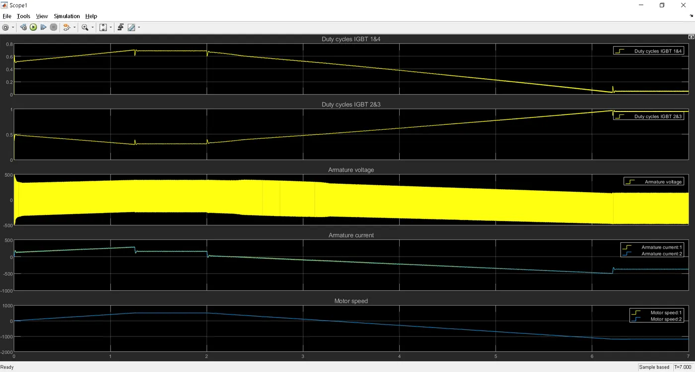
`to`For better understanding, i have separately connected scopes to armature voltage and motor speed.
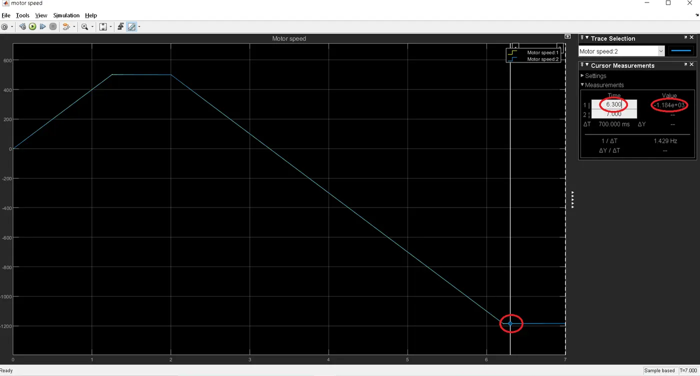
`to`The speed reference is set at 500 rpm at t = 0 s.
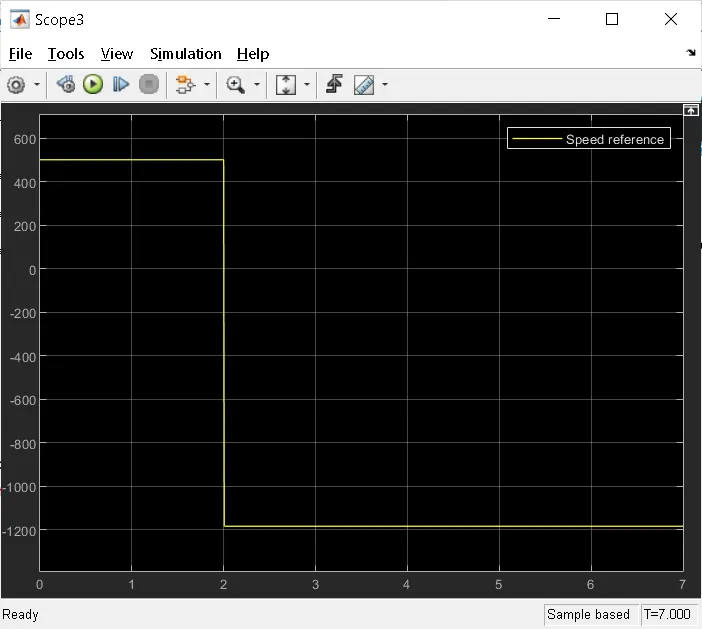
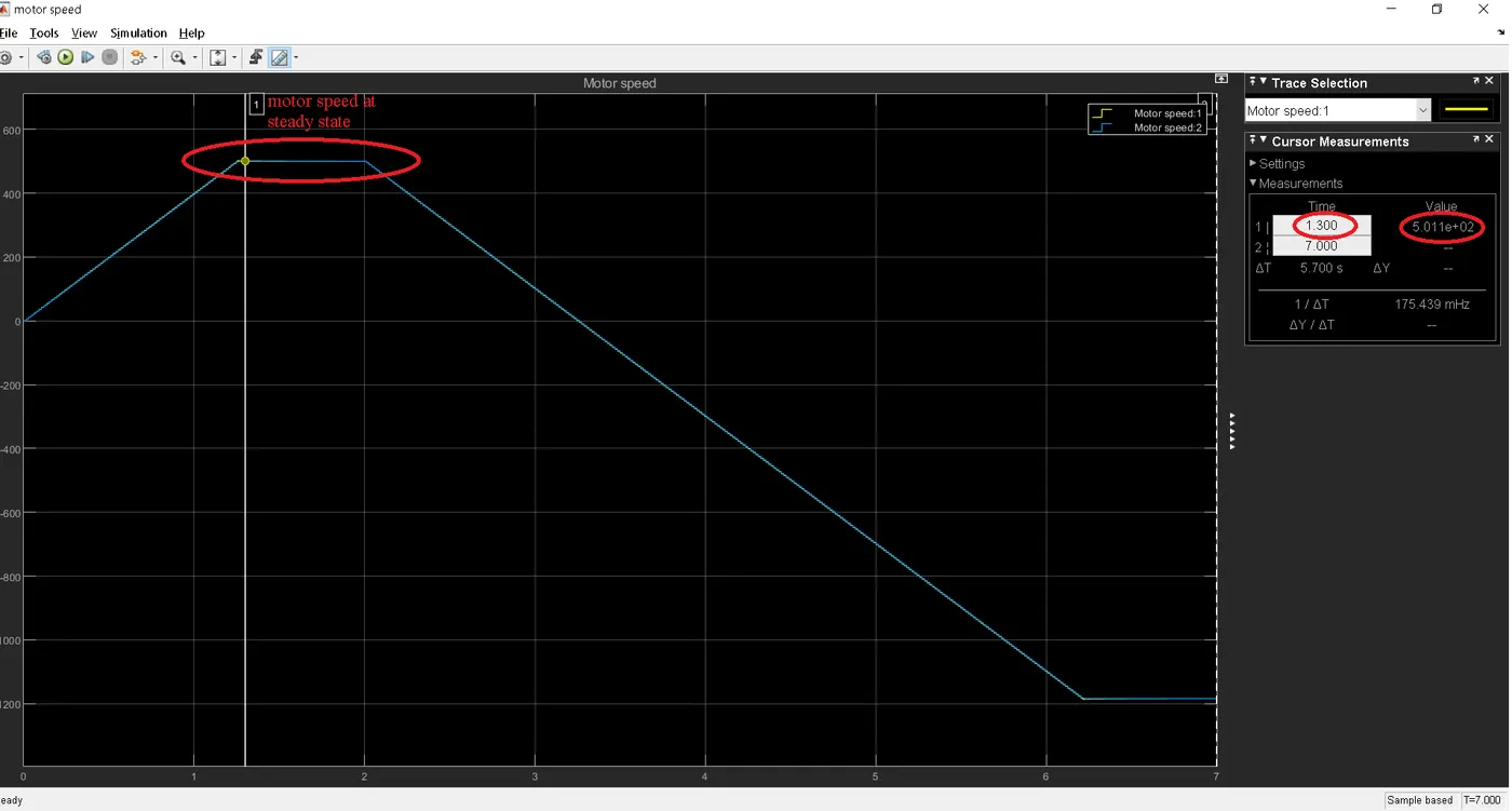
`to` Observe that the motor speed follows the reference ramp accurately (+400 rpm/s) and reaches steady state around t = 1.3 s
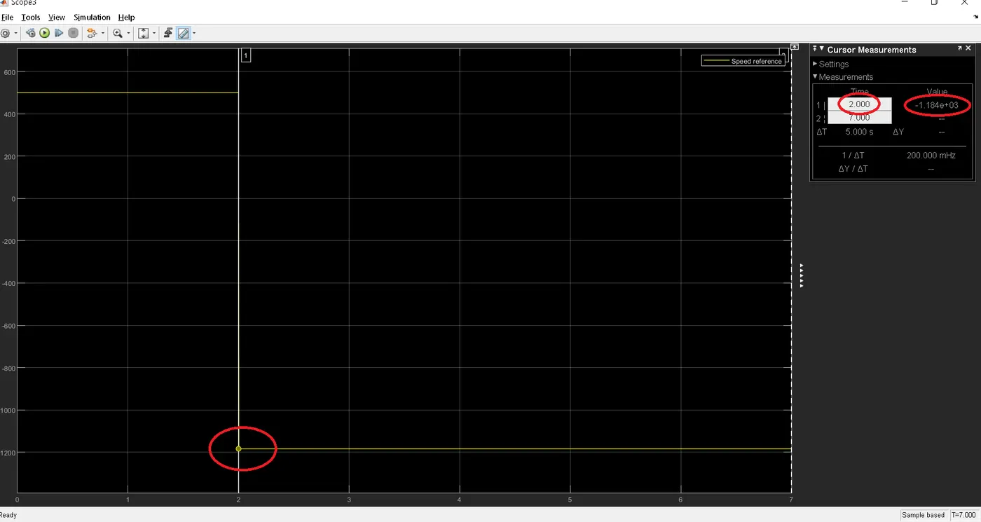
`to`At t = 2 s, speed reference drops to -1184 rpm. The current reference decreases to reduce the electromagnetic torque and causes the motor to decelerate with the help of the load torque.
`to`At t = 3.25 s, the motor reaches 0 rpm and the load torque reverses and becomes negative. The negative current now produces an accelerating electromagnetic torque to allow the motor to follow the negative speed ramp (-400 rpm/s). 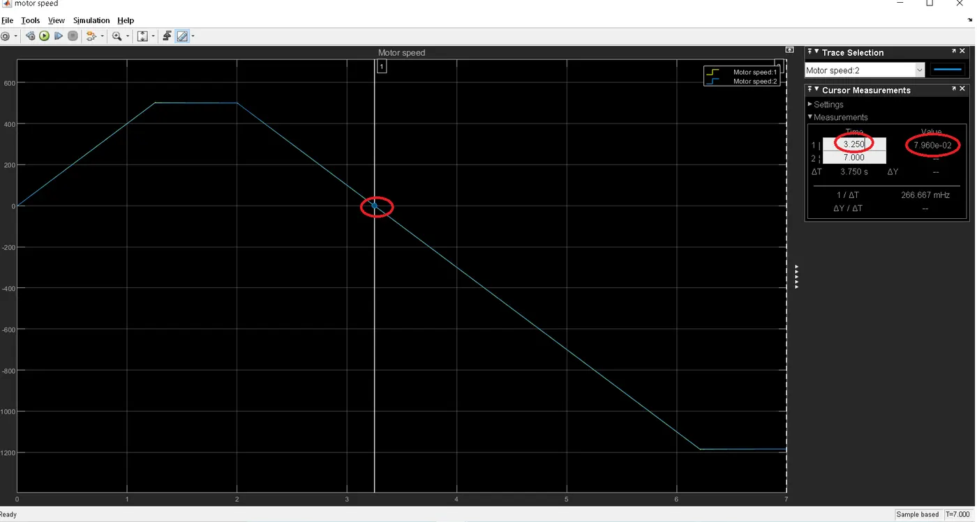
`to`At t = 6.3 s, the speed reaches -1184 rpm and stabilizes around its reference.
Comparison -
|
DC drive using BJT H-bridge |
DC drive using Four-Quadrant Chopper |
|
|
|
|
|
|
|
|
|
|
|
|
REFERENCE
for four quadrant DC operation - https://circuitglobe.com/four-quadrant-operation-of-dc-motor.html
------------------------------------------------------------------------------------------------------------------------------------------------------------------------------------------------------------------------------------------------------------------------------------------------------------------------------------------------------------------------------------------------------------------------------------------------------------------------------------------------------------------------------------------------------------------------------------------------------------------------------------------------------------------------------------------------------------------------------
OBJECTIVE-3`to`Make a suitable EV model using DC7 block and make result report.
`to`To design an ev model using the DC7 block. We have to make certain changes.
`to`I have replaced the speed reference with my custom made drivecycle.
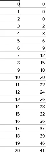
`to`The 380V 50Hz AC 3 phase supply is replaced by a simple DC source.
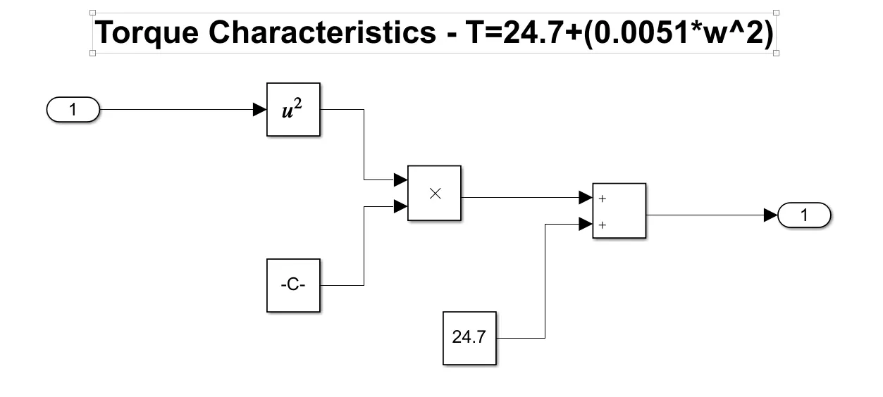
`to`The load applied on the DC7 model was linear, so i replaced it with a torque characteristics governed by the equation - `T_L=24.7+0.0051*w^2`. This has been showcases as a subsystem.
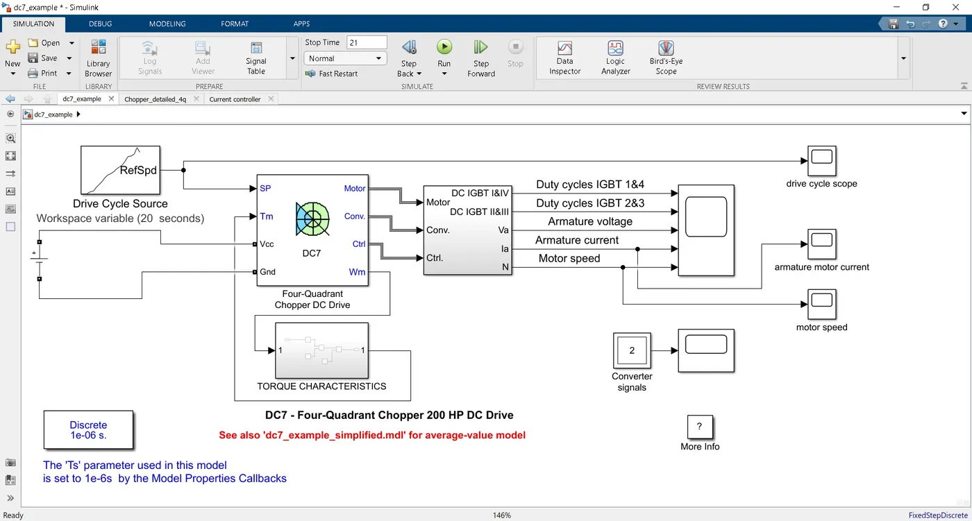
`to`The EV Model is as shown below -
OUTPUT -
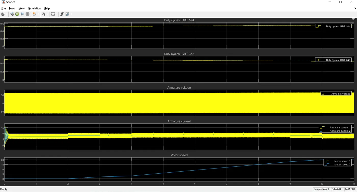
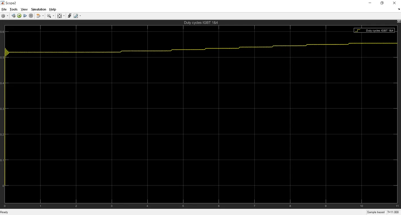
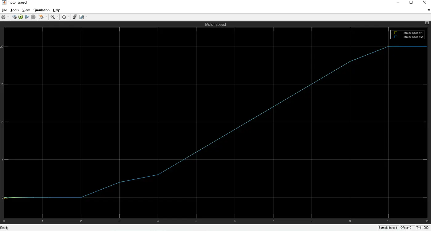
`to`IGBT 1 & 4 - Initially, there is huge rise in dutycycle, around 0.53. Then it is in constantly rising. The initial rise can be compensated to start the motor. Throughtout the duty cycle is inreasing in pulses, because the motor speed is continously increasing and it is maximum at t=10s
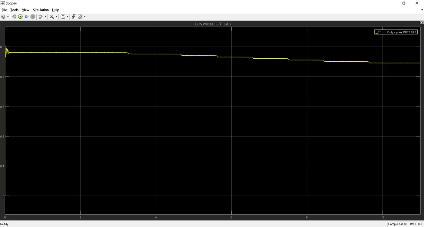
`to`IGBT 2 & 3 - They are mirror image of the above plot.
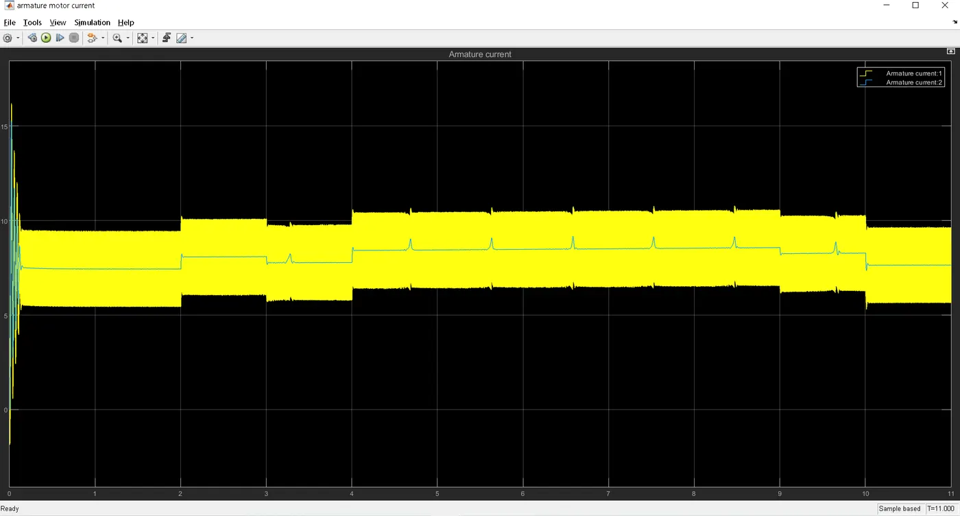
`to`Armature Current -
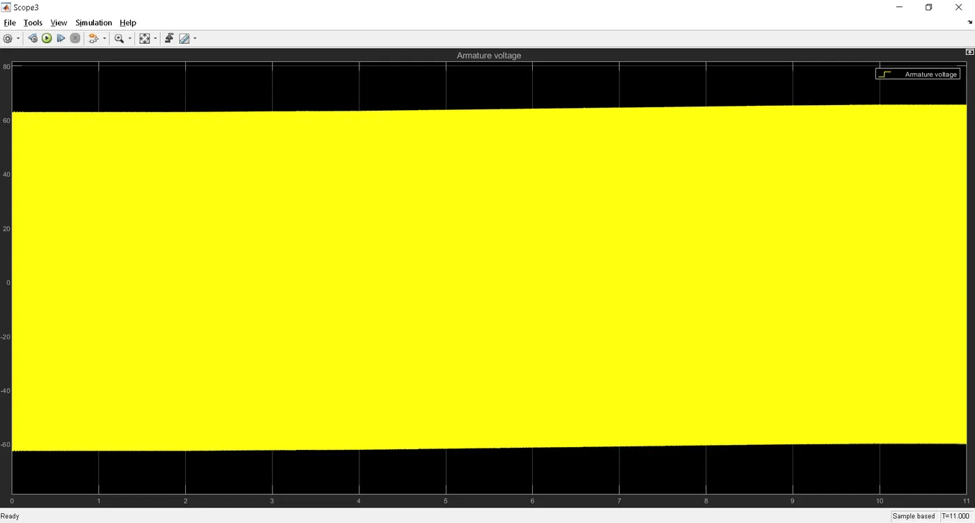
`to`Armature Voltage -
`to`Motor Speed -
REFERENCES