Electric Doorbell Design & Thermistor for Heater Design
AIM-1
Designing a Simulink model of Doorbell. Create a situation where the switch is closed for 2 seconds and then released. Observe the physical movement of the plunger.
REQUIREMENTS
MATLAB & SIMULINK softwares
Simulink - is a graphical user interface for modeling and simulation of block schematics. The core of the Matlab is used to compute the simulating results. Simulink is primarily used for modeling dynamic systems. Simulink’s libraries offer a plenty of blocks useful for modeling complex systems. With help of integrating methods, we can simulate the system and analyze it in time.
Simscape – is a library of basic real world mechanics, hydraulics and electronics components. System, built from these blocks, is modeled from view of energy flow. Model works directly with physical parameters, so it approximates good real systems. Simscape generates differential equations from the modeled system that can communicate with other components from Matlab/Simulink after the simulation has been started.
THEORY
The electric doorbell is a simple circuit that triggers a sound on the completion of circuit by pressing the button. It is this simplicity that makes doorbell such a marvel. The simple devices in the doorbell put the scientific principle of electromagnetism into action in a useful way. In order to understand the operations of an electric bell, you should first need to understand what is electromagnetism. Well, to put it in simple words, an electromagnet is basically a type of magnet in which the magnetic field is produced with the help of an electric current. When any electrical influences electromagnet it works as a standard magnet (generating magnetic fields). When the power generation to an electromagnet stops, the production of the magnetic field also stops.
So, in an electric bell, an electromagnet forms an important part along with Armature, Spring, Armature rod, Hammer and a Gong.

An electric source, for example, a battery can be used to power the electromagnet used in an electric bell. The electric circuit is completed by installing a push switch which you can press to sound an electric bell. The switch also acts as the circuit breaker.
So once the setup is completed, when the switch is pressed, the circuit loop is complete which causes the current to flow through the circuit. The arm which strikes the gong is connected to a spring at one end and an iron ball at the other end. This is called a hammer or a striker. The arm is attached to an iron strip which is attracted to the electromagnet when the circuit is complete and the current flowing through it.
Why does this happen? It’s mainly because the magnetic field created by the electromagnet attracts the iron strip towards it when the circuit is complete. This is the moment when you hear the ringing sound since the hammer keeps hitting the gong. Meanwhile, at its rest position, the hammer is held away from the gong on account of the spring attached to its arm. This is an anchored arm.
Process of the working of an electric bell
Now that you have an understanding of the important parts in an electric bell, the step by step process of the working of the electric bell is described below:
- The switch is pressed and current flows through the circuit.
- The electromagnet is powered and generates a magnetic field that attracts the iron strip towards it.
- The striker strikes the gong (bell).
- When the striking arm strikes the gong, the contact is broken and current stops flowing through the circuit.
- This causes the electromagnet to lose its magnetic field.
- The connected spring arm returns the striker to its original rest position.
- The contact is restored and current flows through the circuit (provided the main switch is still pressed).
- The process is repeated from the beginning.
PROCEDURE
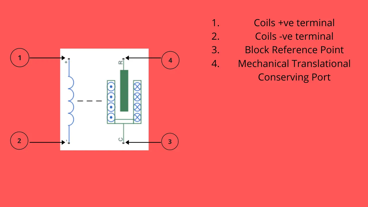
- The first step is to deploy the solenoid block. It can be done from the simulink library or just double click on the screen and typing the keyword'solenoid' in the annotation space provided
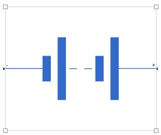
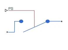
- Then go for battery and a switch that accepts a PS (Physical Signal).
 &
& 
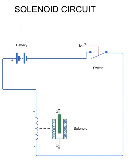
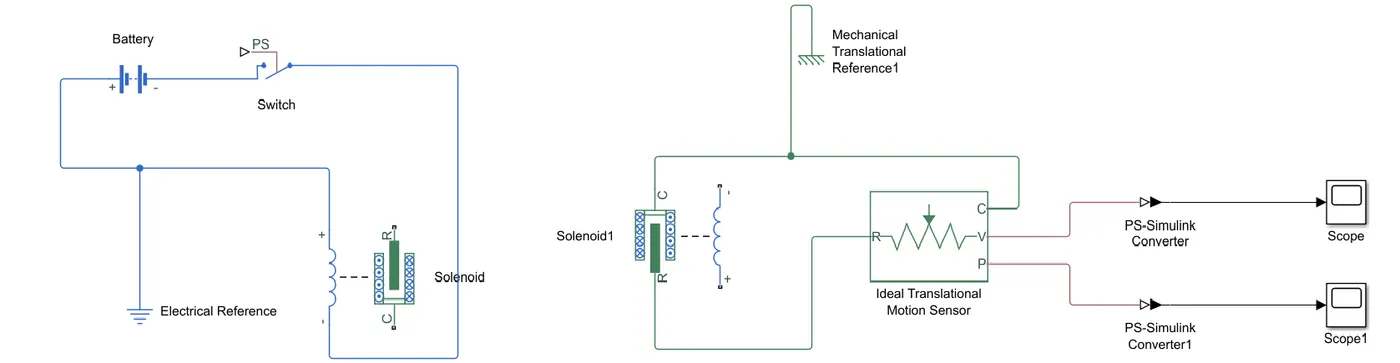
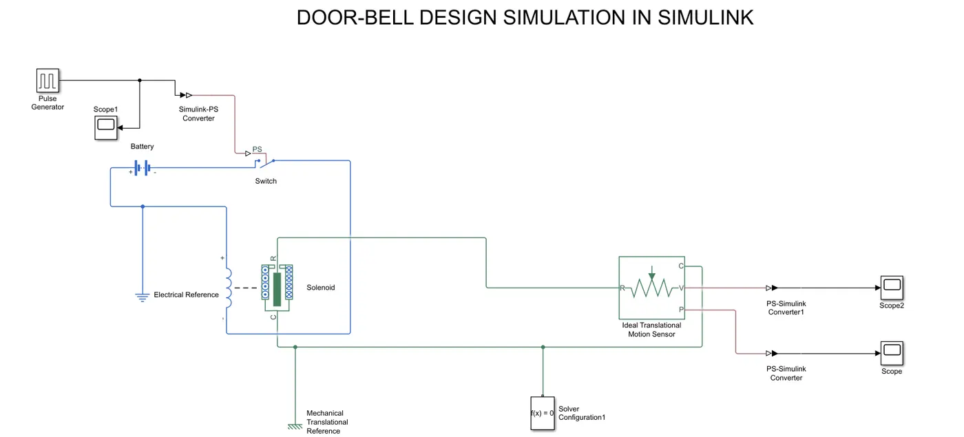
- Now we will conect the block as shown below,
- Now we will connectt the solenoid R & C with a sensor block, because we have to know the position of plunger when the circuit is closed. This can be seen by a ideal translational sensor. This block contains 4 ports.
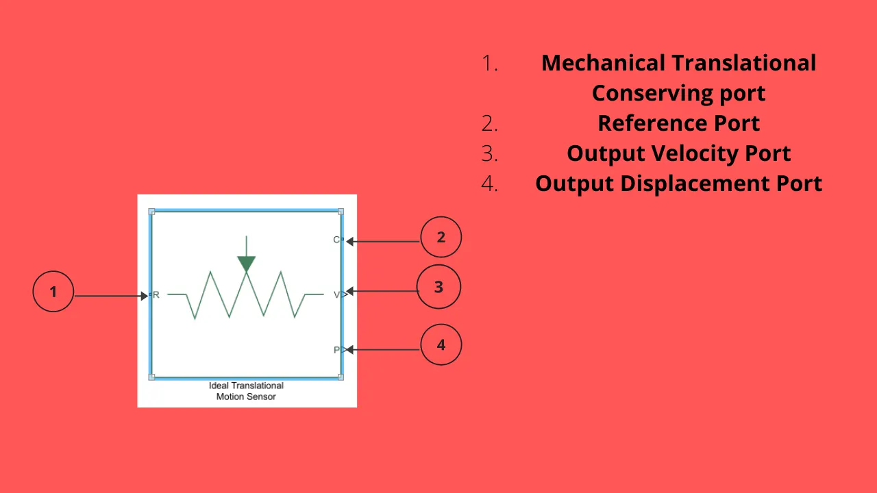
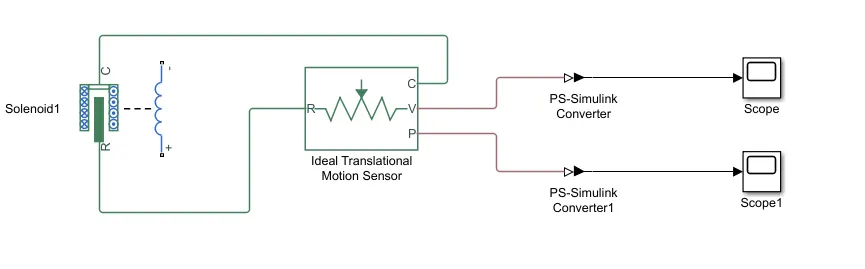
- The solenoids R & C port is connect to the repective ports of the sensor. Along with that for display purpose, we will deploy two 'scope' blocks to the P & V ports of the sensor.
NOTE:- The output from the sensor is a physical signal and to display it in the simulink platform, we have to convert it using a "PS to Simulink converter".
- Now we have to provide the reference block for the circuit. The whole circuit is a combination of electrical and mechanical moving parts. So we will provide an electric resistance to the solenoid-batttery circuit and a mechanical translational reference for the solenoid-sensor connection. The later part is given combinedly to C-ports of solenoid as well as sensor.
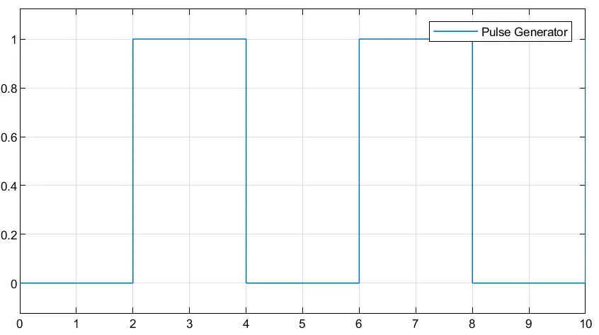
- Now we will provide the input to the switch, so that it switches on and off for the simulation requirement. The switch has 3 ports. Two ports are for the circuit connection and the remaining one is for input. The 3rd input accepts a PS signal. But the software provides the simulink input. Hence a Simulink to PS converter is required. Now the source of input is from a pulse width generator. It will porduce the required frequency distributed signals. In the question it is asked to provide a 2 seconds of pulse delay. So we provide time period as 4sec and the pulse width in % as 50%. This will divide the whole 4 second of time period into two, with the required pulse delay.
Pulse Width Generator ⇒⇒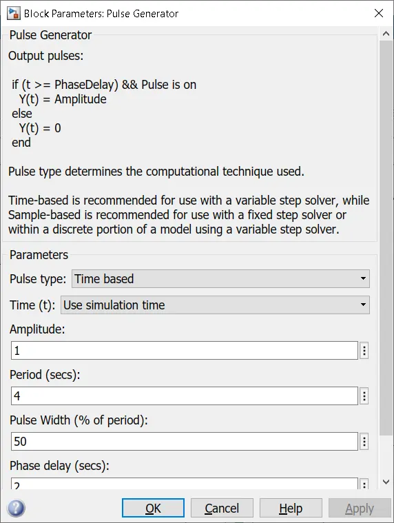 input circuit ⇒⇒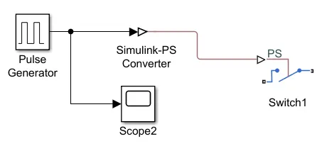
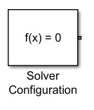
- Atlast we provide a solver configuration. Because in the backend of the Simulink software, there are many equarions undergoing and we are using a simscape model in this design. Hence to give the required compilation of simscape blocks, we need a solver.
WHOLE DESIGN
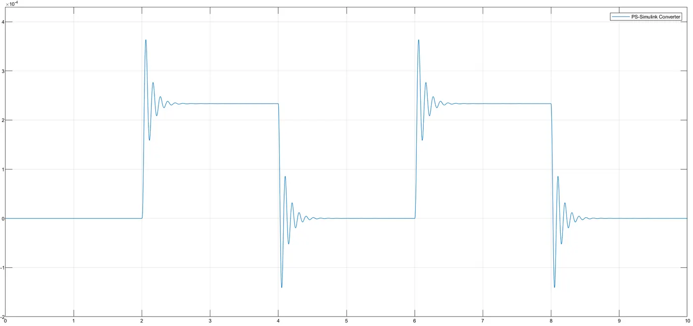
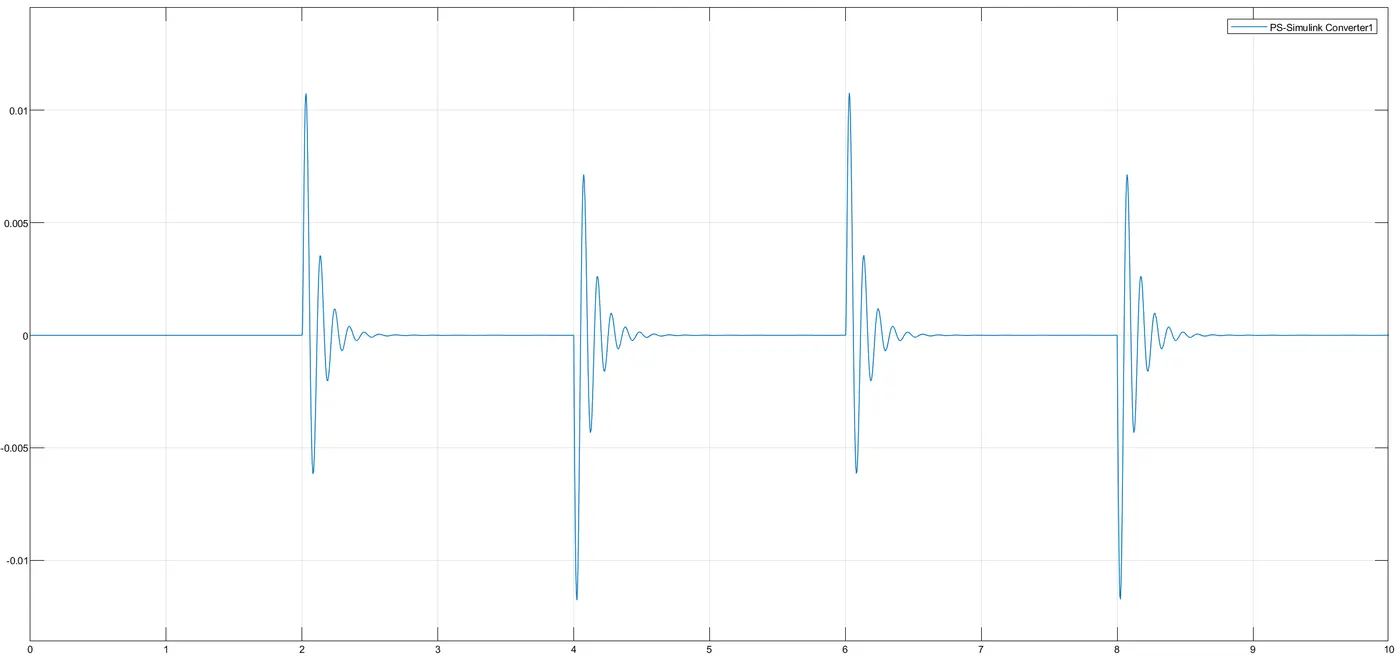
(i.e.) for K=200 and C=1
INPUT SINGNAL⇒⇒
OUTPUT DISPLACEMENT OF PLUNGER ⇒⇒
OUTPUT VELOCITY OF PLUNGER ⇒⇒
- NOTE:- If we want to reduce the disturbances in the above plots, then by decreasing the stiffness and increasing the damping coefficent, we can reduce the disturbances.
(i.e.) for K=100 and C=5
DISPLACEMENT OUTPUT ⇒⇒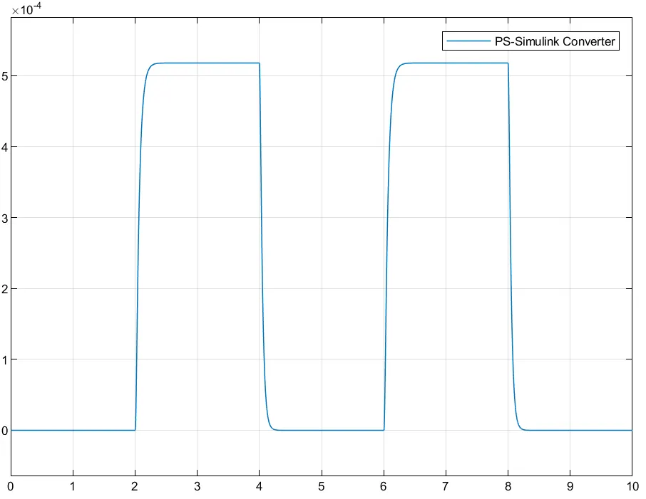 VELOCITY OUTPUT ⇒⇒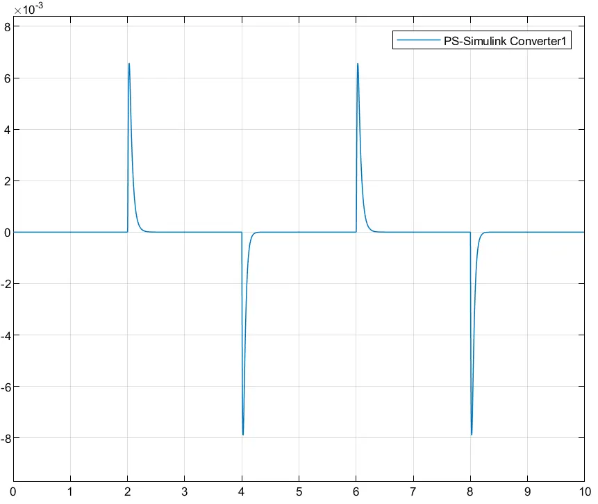
REFERENCE
https://byjus.com/physics/working-of-electric-bell/
https://www.youtube.com/watch?v=HpTp227586s
------------------------------------------------------------------------------------------------------------------------------------------------------------------------------------------------------------------------------------------------------------------------------------------------------------------------------------------------------------------------------------------------------------------------------------------------------------------------------------------------------------------------------------------------------------------------------------------------------------------------------------------------------------------------------------------------------------------------------
AIM-2
Use a thermistor to sense the temperature of a heater & turn on or turn off the fan as per below conditions:-
Temperature source: 20 °C from 0 to 10 seconds,
27 °C from 10 to 30 seconds,
23 °C from 30 to 50 seconds
Fan conditions: ON if the temperature above 25 °C, OFF otherwise
REQUIREMENTS
MATLAB & SIMULINK softwares
Simulink - is a graphical user interface for modeling and simulation of block schematics. The core of the Matlab is used to compute the simulating results. Simulink is primarily used for modeling dynamic systems. Simulink’s libraries offer a plenty of blocks useful for modeling complex systems. With help of integrating methods, we can simulate the system and analyze it in time.
Simscape – is a library of basic real world mechanics, hydraulics and electronics components. System, built from these blocks, is modeled from view of energy flow. Model works directly with physical parameters, so it approximates good real systems. Simscape generates differential equations from the modeled system that can communicate with other components from Matlab/Simulink after the simulation has been started.
THEORY
What is a Thermistor? ⇒⇒ A thermistor (or thermal resistor) is defined as a type of resistor whose electrical resistance varies with changes in temperature. Although all resistors’ resistance will fluctuate slightly with temperature, a thermistor is particularly sensitive to temperature changes.
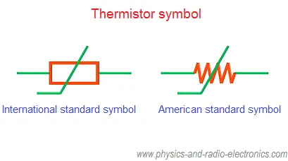
Thermistors act as a passive component in a circuit. They are an accurate, cheap, and robust way to measure temperature. While they do not work well in extremely hot or cold temperatures, they are the sensor of choice for many different applications. They are ideal when a precise temperature reading is required. The circuit symbol for a thermistor is shown below:-
Uses of Thermistors:- Thermistors have a variety of applications. They are widely used as a way to measure temperature as a thermistor thermometer in many different liquid and ambient air environments. Some of the most common uses of thermistors include:
- Digital thermometers (thermostats)
- Automotive applications (to measure oil and coolant temperatures in cars & trucks)
- Household appliances (like microwaves, fridges, and ovens)
- Circuit protection (i.e. surge protectors)
- Rechargeable batteries (ensure the correct battery temperature is maintained)
- To measure the thermal conductivity of electrical materials
- Useful in many basic electronic circuits (e.g. as part of a beginner Arduino kit)
- Temperature compensation (i.e. maintain resistance to compensate for effects caused by changes in temperature in another part of the circuit)
- Used in wheatstone bridge circuits
Working Principle :- The working principle of a thermistor is that its resistance is dependent on its temperature. We can measure the resistance of a thermistor using an ohmmetre. If we know the exact relationship between how changes in the temperature will affect the resistance of the thermistor – then by measuring the thermistor’s resistance we can derive its temperature. How much the resistance changes depends on the type of material used in the thermistor.
PROCEDURE
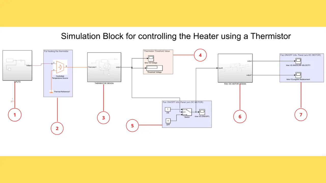
- I have divided the design into 7 subsystems as shown below and each one will be discussed separately.
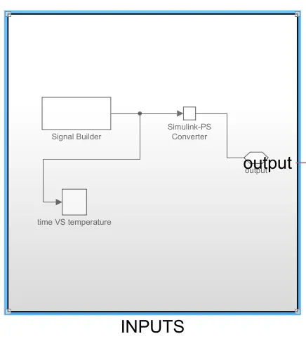
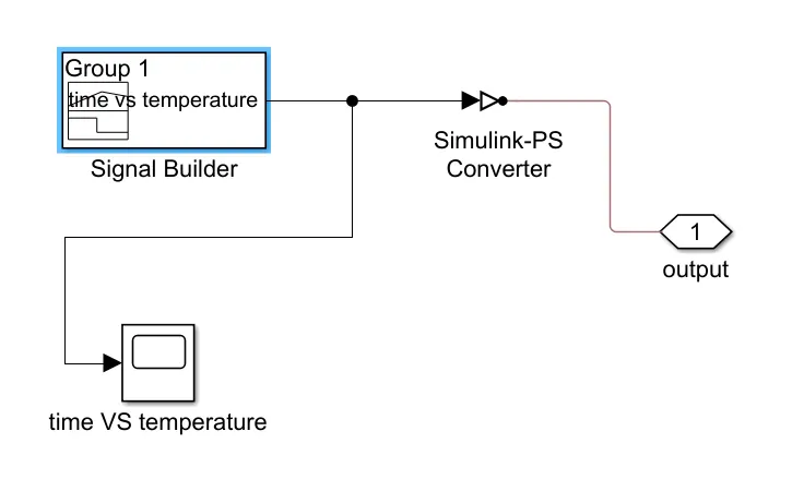
- The first block is the input block, wherein we using a signal builder to give an input that is filtered.i.e
20 °C from 0 to 10 seconds,
27 °C from 10 to 30 seconds,
23 °C from 30 to 50 seconds. The output of this subsystem is coverted into physical signal (PS) by means of a simlink-PS converter. Alon with that a scope is also attached to examine the input.
 ⇒⇒
⇒⇒ 
output⇒⇒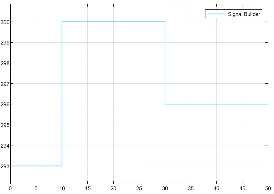
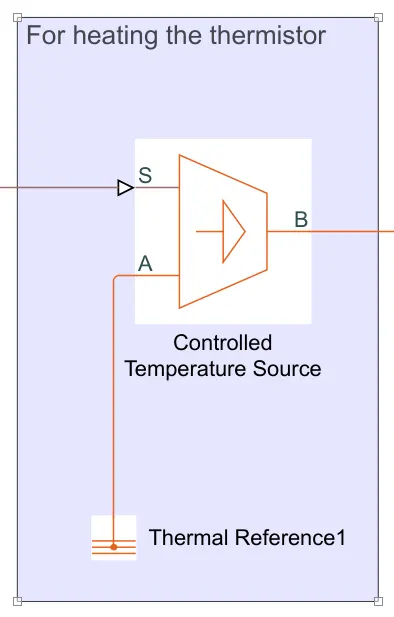
- Now a controlled temperature source that will deliiver the filtered input onto the thermistor in the respective time intervals. It is also grounded to the thermal reference.
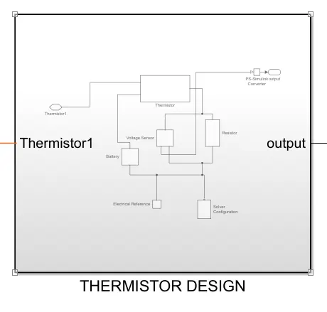
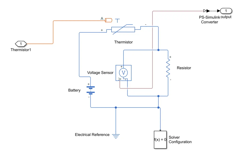
- After that we will have the thermistor design. The thermistor is given the a temperture input, that will vary in specified time intervals. Thermistor is connected to a battery source and a resistor and voltage sensor (i.e. voltmetre) connected in parallel. This voltage sensor and resistance connection is for finding the threshold voltage, which is the triggering value to make the fan ON/OFF. Here it is given as 25∘C25∘C (298K).
 ⇒⇒
⇒⇒ 
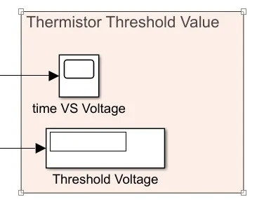
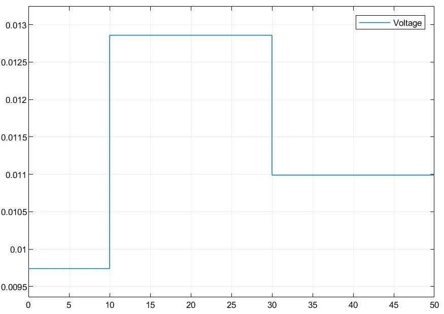
- Then we will, execute the threshold value using a scope and display blocks.
NOTE:- The threshold value is 0.01099
 ⇒⇒
⇒⇒
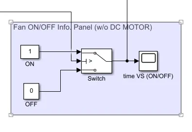
- Now we can either show the required result of switch ON/OFF of the fan by just designing with constants '0' and '1' or by a DC motor as the fan.
By using constants '0' and '1'⇒⇒
 output⇒⇒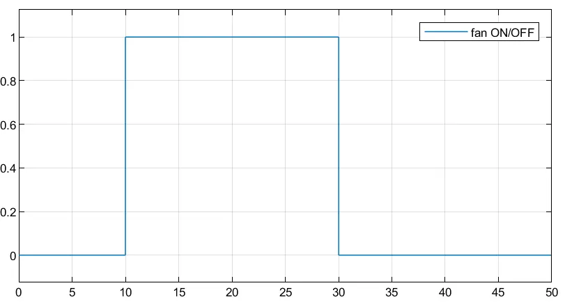
NOTE:- You can see from the plot that till,
(0→→10) sec⇒⇒fan OFF (i.e constant 0),
(10→→30)sec⇒⇒fan ON(i.e. constant 1),
(30→→50)sec⇒⇒fan OFF (i.e. constant 0), because it is said that the fan should be ON only above 25∘C25∘C and that is happening only in (10→→30)sec⇒⇒27∘C27∘C
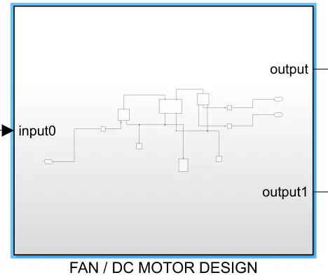
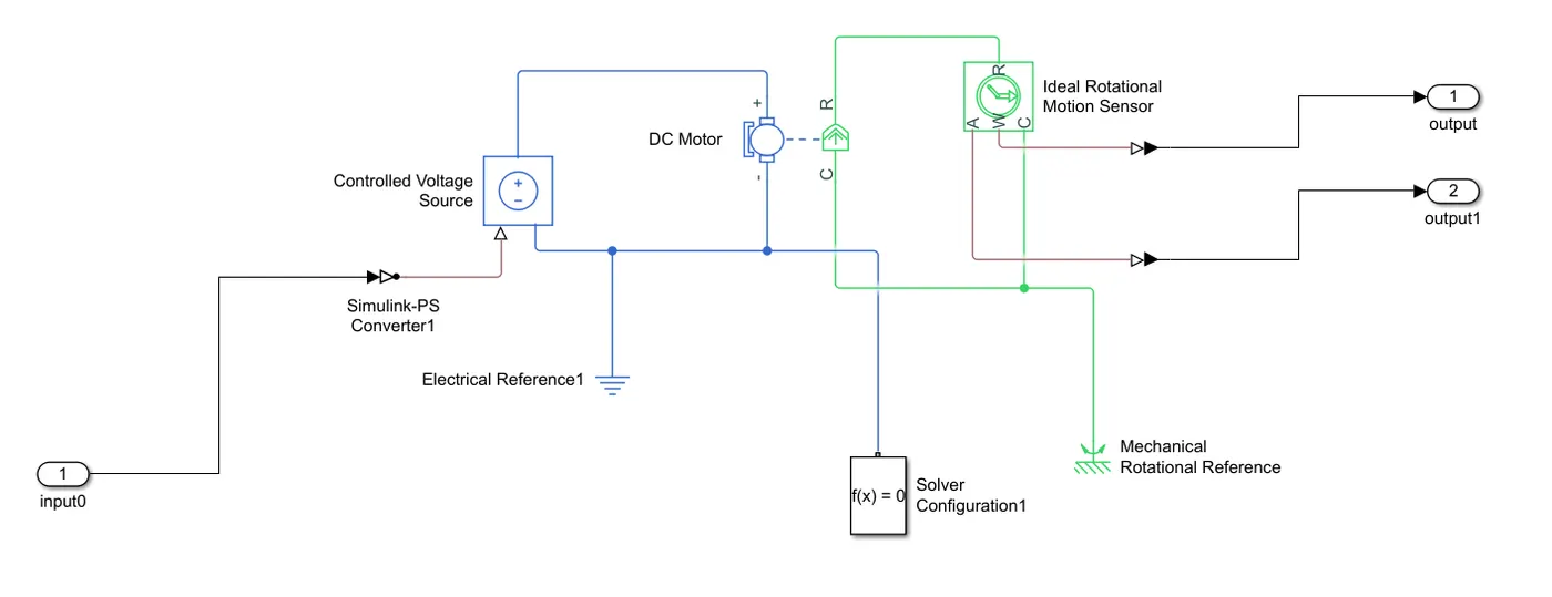
By using the DC Motor ⇒⇒ The dc motor's +ve terminal is connected to a controlled voltage source and the rotary part is connected to an ideal rotational motion sensor. The output is taken from this sensor and it is shown on the scope.
 ⇒⇒
⇒⇒
Now the main output is as shown below:-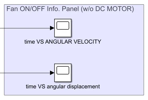
Angular Velocity of fan⇒⇒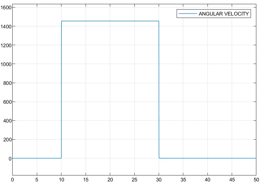
Angular Dispalcement of fan⇒⇒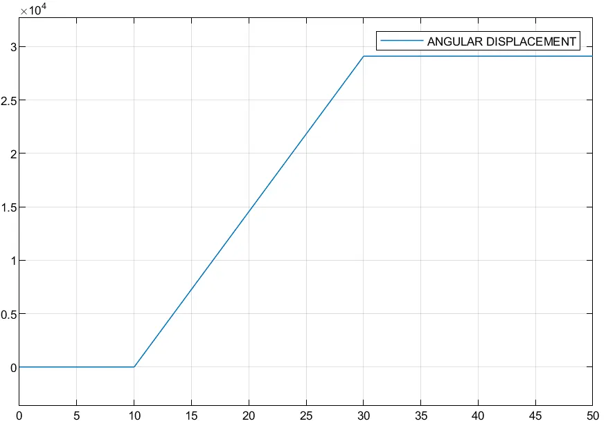
NOTE:- You can see from anguar displacement of fan plot that, in the region (10→→30)sec, it is linear. Therefore the fan is running but n time segments, it is 0. Hence the conditioned is satisfied.
NOTE:- There are two solver configurations provided, as it is a electro-mechanical simulation.
REFERENCES