Week-7 Challenge: DC Motor Control
1. A. Explain a MATLAB demo model named ‘Speed control of a DC motor using BJT H-bridge’.
B. Comment on the armature current shoot-up from the scope results.
C. Refer to the help section of ‘The Four-Quadrant Chopper DC Drive (DC7) block’. Compare it with the H-bridge model.
Answers:-
To know more about the speed control of DC motor using BJT H-bridge,We need to know about the components used in the circuit.
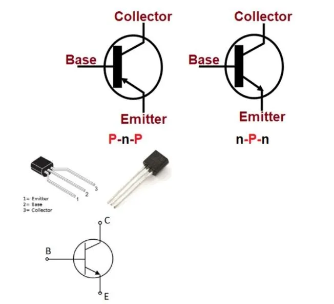
- BJT:-
Bipolar junction transistors (BJT) are current regulating devices that control the amount of current flowing through them from the Emitter to the Collector terminals in proportion to the amount of biasing voltage applied to their base terminal,Thus acting like a current-controlled switch.
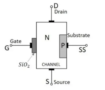
- MOSFET:-
The MOSFET (Metal Oxide Semiconductor Field Effect Transistor) transistor is a semiconductor device which is widely used for switching and amplifying electronic signals in the electronic devices.The MOSFET is a three terminal device such as source,gate,and drain.
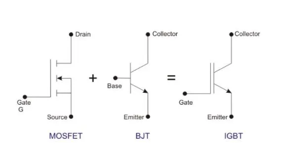
- IGBT:-
An Insulated gate Bipolar Transistor (igbt) is a key component in what makes up a VFD (Variable Frequency Drive).An IGBT is the inverter elements in a VFD,pulsing voltage faster than we can even blink.An IGBT is a semiconductor with three terminals which work as a switch for moving electrical current.Just as the word "gate" suggests,When voltage is applied to the gate,It opens or "turns on" and creates a path for current to flow between the layers.If no voltage is applied to the gate,or if the voltage is not high enough,The gate remains closed and there will be no flow of electricity.In this way,an IGBT behaves loke a switch;on when the gate is open and flowing current and off when it is closed.Thus the IGBT acts as the switch used to create Pulse-Width Modulation (PWM).An IGBT will switch the current on and off so rapidly that less voltage will be channelled to the motor,helping to create the PWM wave.
- Speed control of a DC motor using BJT H-Bridge:-
The Bipolar junction Transistor (BJT) When used for power switching applications and operates as an IGBT.When it is conducting (BJT operating in the saturated region),a forward voltage Vf is developed between collector and emitter (in the range of 1V).Therefore,The IGBT block can be used to model the BJT device.
The IGBT block does not simulate the gate current controlling the BJT or IGBT.The switch is controlled by a Simulink signal(1/0).
The DC motor uses the preset model (5HP 24V 1750 rpm).It simulates a fan type load (Where Load torque proportional to square of speed).The armature mean voltage can be varied from 0 to 240V When the duty cycle(Specified in the pulse generator block) is varied from 0 to 100%.
The H-Bridge consists offour BJT/Diode pairs two transistors are switched simulataneouslyy:Q1 and Q4 or Q2 and Q3.When Q1 and Q4 are fired,a positive voltage is applied to the motor and diodes D2-D3 operate as free-wheeling diodes when Q1 and Q4 are switched off.When Q2 and Q3 are fired,A negative voltage is applied to the motor and diodes D1-D4 operates as free-Wheeling diodes when Q2 and Q3 are switched off.
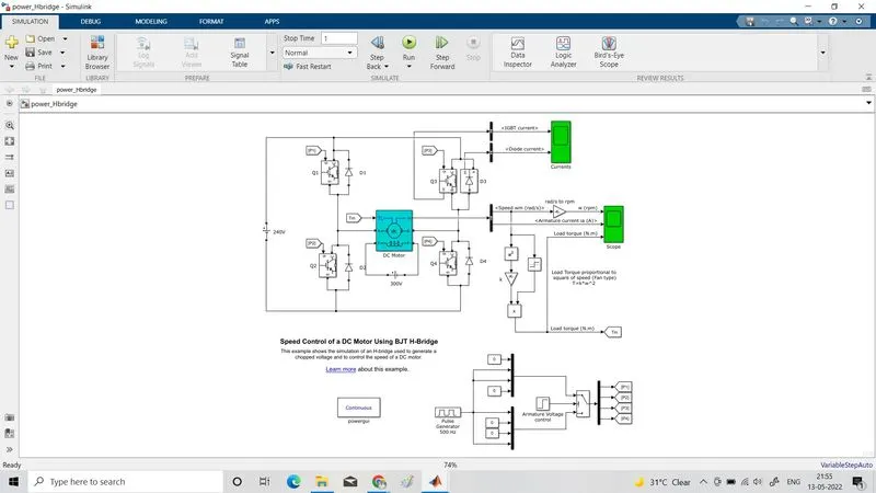
The Pilse generator is used to generate pulses which are fed to the four IGBTs to create pulse width modulation.Here in this model,The silulation is such that the motor starts in the positive direction with a duty cycle of 75% (mean DC voltage of 180V). Scope shows motor speed,Armature current and load torque and Current shows currents flowing in BJT Q3 and diode D3.
Initial the block parametrs for pulse generator are as fallows
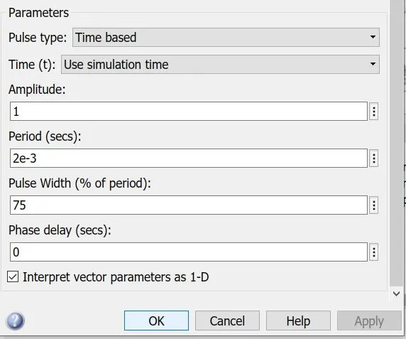
When we run the model,We get the fallowing results
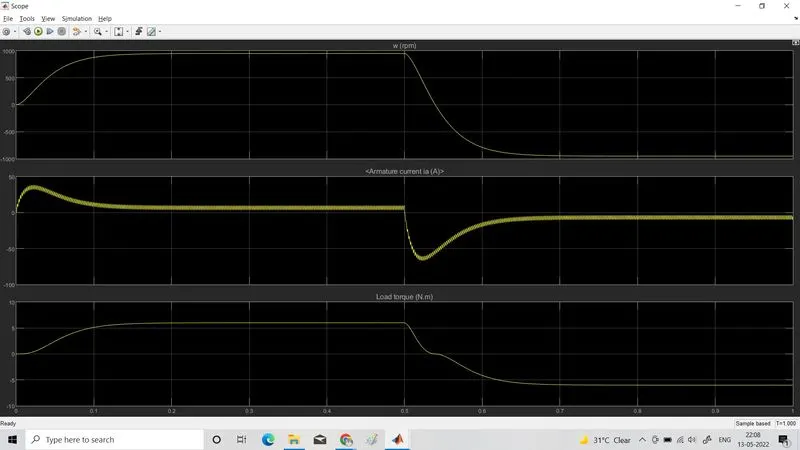
At t=0.5sec,The arature voltage is suddenly revesed and the motor runs in the negative direction.So in the first half cycle,We can see the motor attains a speed of 1000rpm a load torque of 6 N.m where as the second half the same values in the negative directions.Here we can see that the armature current of DC motor does get shoot up.To avoid this,We will have to reduce the pulse width from the pulse generator.
We can modify the model by reducing the pulse width to 40%.
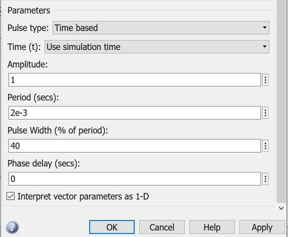
When we run the model after the modification,We get the fllowing results
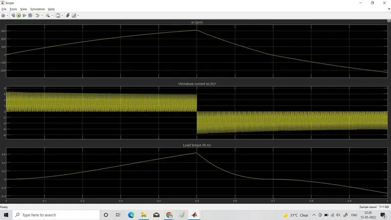
Here we can observe that the armature current is almost 0 A,that means the armature current doest shoot up at 40% pulse width.Also the motor speed and torque is reduced to 300 rpm and 0.6 N.m respectively due to the reuction in pulse width.This indicates that,as we reduse the pulse width,the motor speed and torque reduces and can attain zero at a certain value.
Comparing "The four-Quadrant Chopper DC Drive(DC7) Block" with H bridge model:
| BJT H-BRIDGE DRIVE | FOUR QUADRANT CHOPPER DRIVE |
| It is used for changing the direction of the motor. |
Here the motor can be operated in 4 different modes. |
| Regenerative braking cannot be available. | Regenerative braking can be archived. |
| The source is of fixed DC supply. | The source is an AC supply which can be rectified to DC varying supply. |
| The armature current shoots up during the phase transition. | The armature current doesn't shoot up to the value of BJT H-bridge but for low voltage value,It's Negligible. |
| Less control of the vehicle. | Better control of the vehicle. |
| Signals are continuous. |
Signals are not continuos and they are discrete. |
2. Develop a 2-quadrant chopper using simulink & explain the working of the same with the relevant results. (Refer to article - Multiquadrant operation of motor )
Answer:-
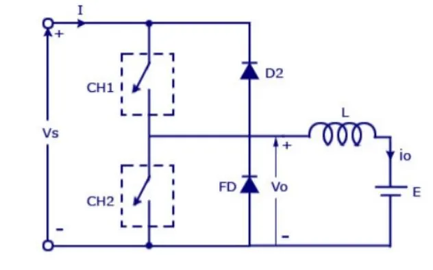
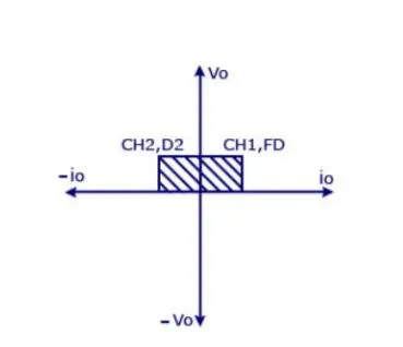
Two quadrant chopper is also called as type c chopper.Type C chooper is obtained by connecting type-A and type-B choppers in parallel.We will always get a positive output voltage V0 as the free wheeling diode FD is present across the load.When the chopper is on the freewheeling diode starts conducting and the output voltage V0 will be equal to Vs.The direction of the load current i0 will be reversed.The current i0 will be flowing towards the sourse and it will be postive regardless the chopper is on or the FD conducts.The load current will be negative if the chopper is or the diode D2 conducts.We can say the chopper and FD operate together as type-A chopper in first quadrant.In the second quadrant,The chopper and D2 will operate together as type-B chopper.
The average voltage will be always positive but the average load current might be postive or negative.The power flow may be life the first quardrant operation ie from source to load or from load to source like the second quadrant operation.The two choppers should not be turned on simulatneously as the combined action my cause a short circuit in supply lines.For regenerative braking and motoring these type of chopper configuration is used.
TWO QUADRANT CHOPPER MODEL USING SIMULINK:
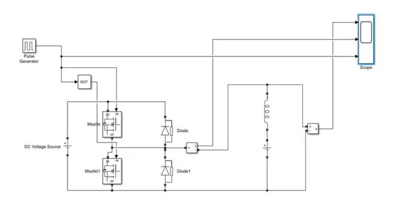
Let us take two MOSFET blocks and diodes blocks and conect it as shown in circuit diagram.
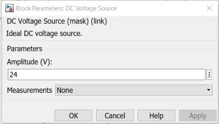
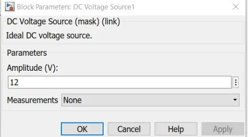
The DC voltage source is connected as shown.
Let the voltage of DC voltage source be 24 volts.
Let us consider an series RLC branch block and select inductor L.Thus block works as a load.To consider LE load ie motor load,and DC voltage source of 12 volts is also connected in series with inductor.
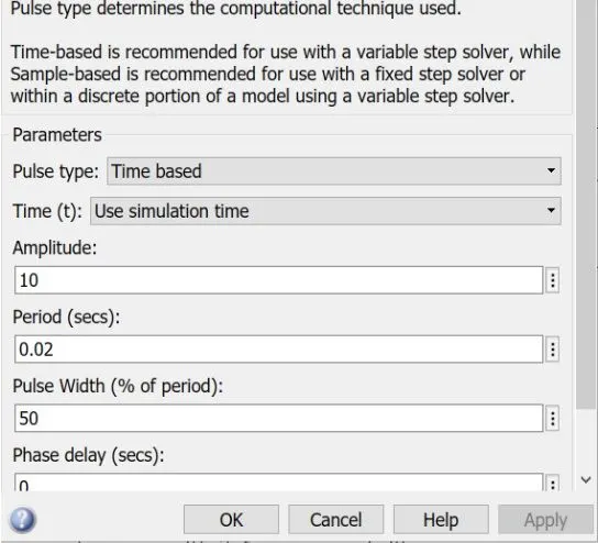
The pulse generator block is useed to create gate pulse.
The not gate is used in the model so that the two MOSFET will not get closed at the same time otherwise short circuit will occour.Due to use of not gate,When one MOSFET is ON the other MOSFET will get off and when other MOSFET is ON the first MOSFET will get OFF.
The amplitude of pulse generator is kept 10 so that we can clearly see the pulses at scope and let period be 0.02 sec and let pulse weidth be 50%.
SCOPE RESULT:-
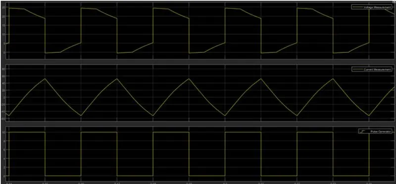
The voltage wave form is not going less than zero.The minimum value of voltage is zero and maximum value is always in the positive direction.
However in current waveform,The current increses and decreases.The current may be positive as well as negative.
The pulse amplitude is 10 thus from pulse waveform we can see that the pulse amplitude is 10.
3. Explain in a brief about operation of BLDC motor?
Answer:-
Brushless DC electric motors also known as electronically commutated motors.A brushless DC motor is a permanent magnet synchronous electric motor which is driven by direct current (DC) electricity and it accompilishes electronically controlled communication sysytem instead of a mechnically communication system.BLDC motors are also referred as trapezodial permenent magnet motors.
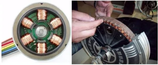
Advantages of BLDC motor:-
- Less overall maintenance due to obsence of brushes.
- Reduced size with far superior thermal characteristices.
- Higher speed range and lower electric noise generation.
- It has no mechanical commutor and associated problems.
- High efficiency and high output power to size ratio due to the use of permananet magnet rotor.
- High speed of operation even in loaded and unloaded conditions due to the absence of brushes that limits the speed.
- Smaller motor grometry and lighter in weight than both brushed type DC and induction AC motors.
- Long life as no inspection and maintance is required for commutator sysytem.
- Higher dynamic response due to low intertia and carrying winding in the stator.
- Less electromagnatic interference.
- Low noise due to absence of brushes.
Disadvantages of BLDC motor:-
- These motors are costly.
- Electronic controller required control this motor is expensive.
- Requires comlex drive circuitry.
- Need of additional sensors.
Application of BLDC motor:-
- Computer hard drivers and DVD/CD players.
- Electric vehicles,hybrid vehicles,and electric bicycles.
- Industrical robots,CNC machine tools,and simple belt driven systems.
- Washing machines,compressors and dryers.
- Fans,pumps and blowers.