Week-6 Challenge: EV Drivetrain
1. Which types of power converter circuits are employed in electric and hybrid electric vehicle?
Answer:-
There are three types of power converters are mostly use in electric & hybrid EV.There are
1) AC to DC converters(Rectifiers):-
These converters are use in plugin EV &HEV for charging DC battery from AC source.Its called the "ON Board charger" through it really is a converter.It converts power from AC to DC and then feeds it into the car's battery.This is the most common charging method for electric vehicles today and must chargers use AC power.
2)DC to DC converters(Choppers):-
Choppers are use where vehicles has DC motors,DC supply from battery is converted into variable DC control the speed of motor,They are called DC drivers.DC to DC converters are used to reduse High voltage DC input to low voltage DC output for some specific appliances.They are also used to isolate some highly sensitive components in a circuit from other components of the circuit to avoid any kind of damage.
3)DC to AC converters(Inverters):-
These converters are use if EV or HEV has AC inductor motor,DC supply from battery is converted into variable AC to run the motor in variable speed,This device is known as VFD.The DC to AC converter is required to convert the DC power to a sutaible AC power for electrical machine the power output from the battery pack (DC current) is converted using inverter to be used in electric motor (AC Current) Converts direct current from the battery to alternating current to be used by other devices such as the traction motor and coolant pump.
2. An Electric Vehicle's powertrain with 72V battery pack in shown in the diagram below. The duty ratio for acceleration operation is 'd1' and for the braking operation the duty ratio is 'd2'.
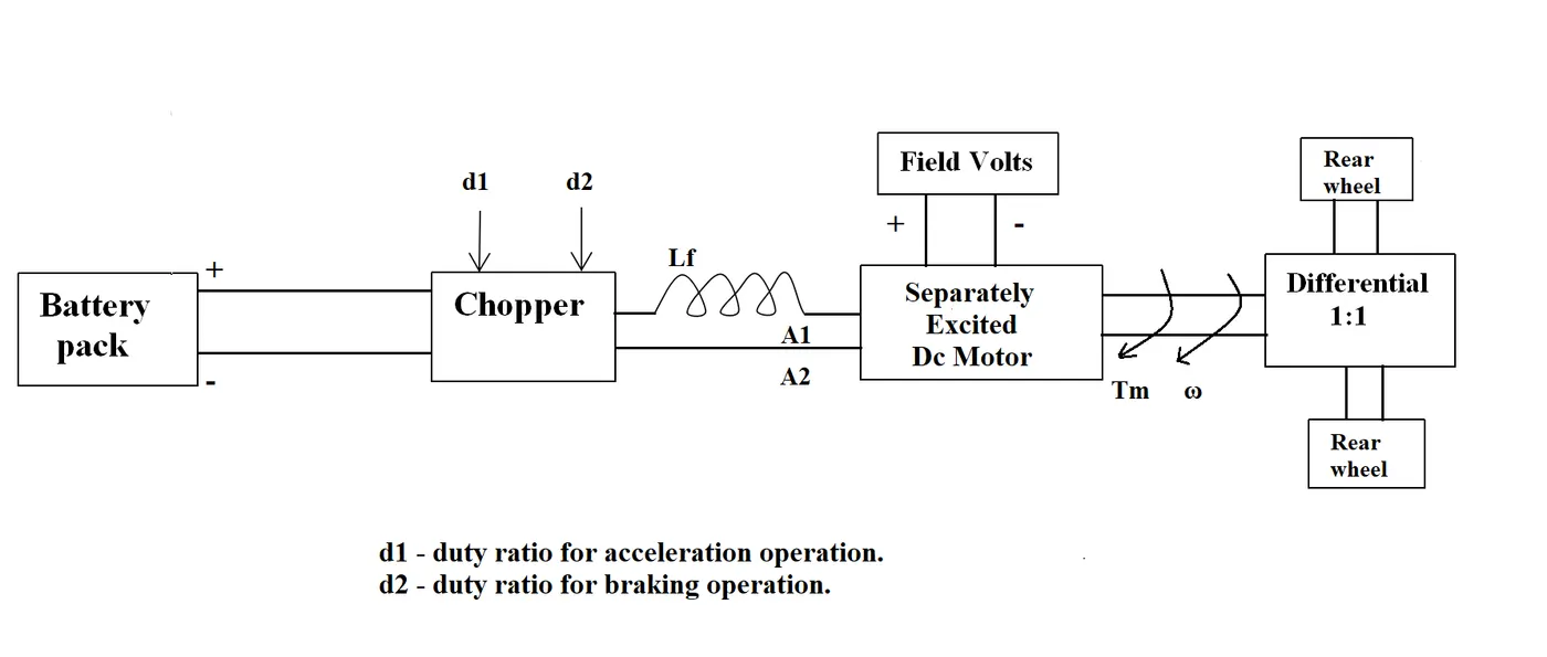
The other parameters of the electric vehicle is given below,
Motor and Controller Parameters:
Rated Armature voltage= 72 V
Rated armature current= 400 A
Ra= 0.5Ω, KΦ= 0.7 Volt second
Chopper Switching frequency= 400 Hz
The vehicle speed-torque characteristics are given by the below equation

What is EV steady state speed if duty cycle is 70%?
Answer:-
Theory:-
V output = V battery*d,
Where d is suty cycle
Then Voutput substituted in equation of DC motor torque and speed
Where,
=angular speedin(radian/sec)
Ra=armature resistance
=motor constant(volt sec)
T=torque(Nm)
Then we get the equation sustituting the all the values amd get the equataion in terms of T and `w` of motor and vehicle torque equation is given in terms of T and `w` at steady state torque at vehicle and torque at motor is equal with that condiation we find `w`
Then implement a code:
clear all
close all
clc
%input parameter
fprintf("Input Parameter n")
Va = input("Enter the Va battery or Aremature voltage(volt) = ") ;
Ia = input("Enter the Ia Armature current (Ampere) = ") ;
Ra = input("Enter the Ra resistance (ohm) = ") ;
Kphi = input("Enter the Kphi motor constant (volt sec)= ");
d = input("Enter the d duty cycle (in percentage)= ");
f =400; %chopper switching frequency (Hz)
%% duty cycle (d),Vo output voltage,Va battery voltage
d1 =d/100 ; % 70 percent
Vo = Va * d1;
%%Tm torque for motor and O omega angular speed
syms('Tm','O')
eqn = Tm ==((Vo - ( 0.*Kphi)).*Kphi)./Ra ;
s1 = solve(eqn);
fprintf("n")
fprintf("Equation of motor Tm = %s n",s1);
%%Tv torque for vehicle
%Tv = 24.7 +(0.0051*(0.^2));
eqn1 = 24.7 + (0.0051*(0.^2));
%at steady state Tm = Tv
syms('O')
eqn2 = s1 == eqn1 ;
s2 = vpasolve(eqn2,[O]);
s2 rpm = (s2(2)*60)./(2*3.14);
fprintf("n")
fprintf("EV steady state speed n if duty cycle is 70 percentage = %f radian/sec %f RPM",s2(2),s2rpm)
RESULT:-
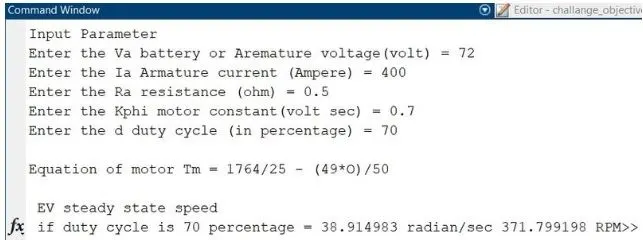
3. Develop a mathematical model of a DC Motor for the below equation using Simulink.
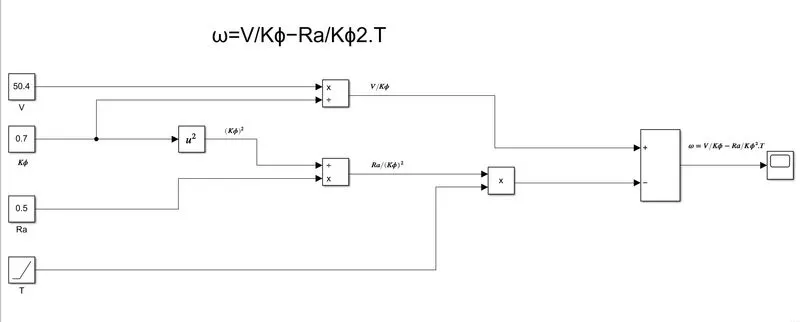
ωω= V/Kϕϕ -Ra/Kϕϕ^2 .T
Answer:-
Model:-
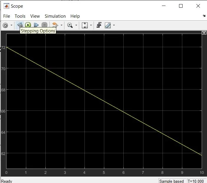
Result:-
4. Refer to the blog on below topic:
Induction Versus DC brushless motors by Wally Rippel, Tesla
Explain in brief about author’s perspective.
Answer:-
Wally rippel forst explain working of brushless DC motor & AC induction motor.
Brush DC motor,The rotor includes two or more permenent magnets that generates a DC magnetic filed(As seen from the vantage point of the rotor).In turn,this magnetic field enters the stator core(a core made up of thin,stacked laminations)and interacts with currents flowing within the winding to produce a torque interaction between the rotor and stator.As the rotor rotates,it is necessary that the magnitude and polarity of the stator currents be continuosuly varied-and in just the right way-such that the torque remains constant and the conversion of electrical to mechinaical energy is optimally efficient.The device that provides this current control is called an inverter.Without it,brushless motors are useless motors.
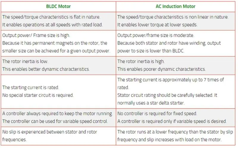
His conclusion is that DC brusless drivers will likely continue to dominate in the hybrid and coming plug in hybrid markets,and that induction drivers will likely maintain domaince for the high performance pure electrics.The hardware iscommon for both drives could mean that we will see induction and DC brushless live and work side by side during the coming golden era of hybrid and electric vehicles.