Week -2
1) Make a Simulink model of Doorbell using solenoid block with the following details:
In the above arrangement, when the switch is closed the electromagnet receives electrical power from the battery and pulls the metal arm to hit the bell producing sound.
Create a situation where the switch is closed for 2 seconds and then released. Observe the physical movement of the plunger.
ANSWER:-
AIM:-
To make a simulink model of doorbell using solenoid block.
Theory:-
DOORBELL:-
- The doorbell is a device having electrical and mechnical compenents produce sound on pressing the button.
- When the switch is pressed,The circuit loop is complete which causes the current to flow through the circuit.whlie passing the solenoid it generates the electromagnet at desired space,which allows the plunger to move due to which it hots the bell and produce the sound.
SOLENOID:-
A Solenoid is a device compresied of a coil of wire,housing,and a moveable plunger(armature).When an electrical current is introduced,a magnetic filed forms around the coil which draws the plungeer in.More simply,a solenied converts electrical energy into mechnical work.
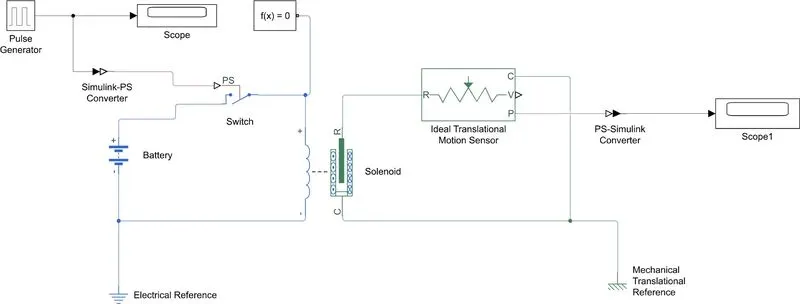
SIMULINK MODEL FOR DOORBELL:-
EXPLANATION:-
In simulink we use blocks to any system to get the desired output.In this project we use some blocks to get our desired output.
- Pulse Generator: The pulse generator block generate square wave pulses at regular intervals.The block wave form parameters,Amplitude,Pulse Width,Period and Phase Delay determine the shape of the output waveform.
- Simulink -PS-Convertor: It converts the Simulink input signal to Physical signal output.
- Switch: Switch is controlled by a external physical signal.
- Battery: It gives the power to close loop.
- Electrical Referance:-It shows connection to electrical ground.
- Solenoid:-Electrical characteristices & Generated force of solenoid.
- Ideal Translational Motion Sensor:-It is a motion sensor in mechanical translational systems.
- PS-Simulink Convertor:-It converts Physical input signal to simulink output signal.
- Mechanical Translational References:-Referance connection for mechnical translational ports.
- Scope:-It displays the signals generated during simulation.
OUTPUT:-
- The Spring constant is 20 N/m.
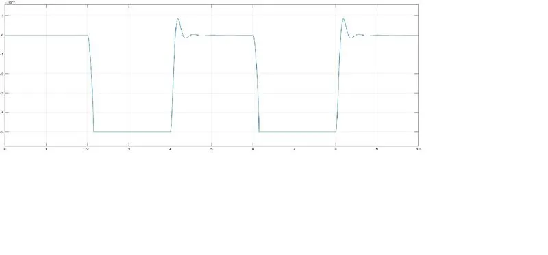
- The Spring constant is 200N/m.
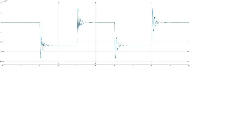
- From the above two graphs we can observe the plunger is moved from its original position to some amplitude with a time delay of 2 sec.
- Then it hits the bell and pause there for 2 sec and comes to its initail position.
2. Use a thermistor to sense the temperature of a heater & turn on or turn off the fan as per the below conditions:
Temperature source: 20 °C from 0 to 10 seconds, 27 °C from 10 to 30 seconds, 23 °C from 30 to 50 seconds
Fan conditions: ON if the temperature above 25 °C, OFF otherwise
Answer:-
THERMISTOR:-
A thermistor is defined as a type of resistor whose electrical resistance various with change in temperature.Althrough all resistors resistance will fluctuate slightly with temperature,a termistor is practiculalary sensitive to temperature changes.The working principal of a thermistor is that its resistance is dependent on its temperature.We can measure the resistance of a thermistor using an ohmmeter.
There are two types of thermistors:
- Negative temperature coefficent thermistor (NTC)
- Postive temperature coefficent thermistor (PTC)
In an NTC thermistor,When the temperature increases ,resistance decreases.And when temperature decreases,resistance increases.Hence in an NTC thermistor temperature and resistance are inversly proportional.This is the most common type thermistor.
In an PTC thermistor,The reverse relationship between temperature and resistance,When temperature increases the resistence also increases,And when the temperature is decreases,then the resistance also decresases.Hence in a PTC thermistor the temperature and resistance are inversely proportional.Althrough the PTC thermistors are not as common as NTC thermistors.There are frequently used as a form of circuit protection.Similar to the function of fuses,PTC thermistors are act as current limiting devices.
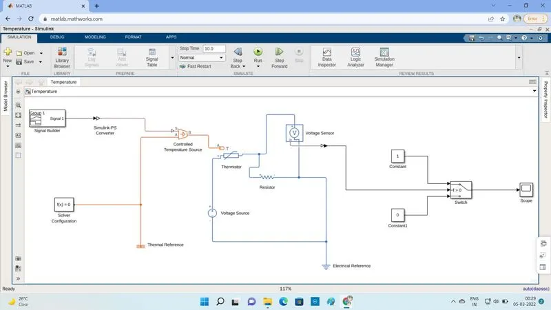
SIMULINK MODEL:-
USED BLOCKS:-
- Signal Builder:- This block allows you to create interchangeable groups of piecewise linear signal sources and use them in a model.You can quickley the signal groups into and out o a model to facelitate testing.In the signal builder window create signals and define the output waves.
- Simulink PS-Convertor:- The block converts the input simulink signal into a physical signal.Use this block to connect simulink sources or other simulink blocks to the inputs of a simscape physical network.
- Controlled Temperature Source:- This block represents an ideal source of thermal energy this is powerful enough to maintain the speccified temperature difference across the source regardless of the heat flow consumed by the system.
- Thermal Reference:- This block represents a thermal referance point,that is,a point with absolute zero temperature,with respect to which all the temperatures in the system and determined.
- Thermistor:- This block represents an NTC thermistor which senses the temperature with respect to time.
- Battery:- The block implements a generic dynamic model that represents the most popular types of rechargeable batteries.
- Voltage Source:- The Voltage source block implements a voltage source with DC, AC,and Noise components.
- Voltage Sensor:- The voltage sensor block represents an ideal voltage sensor,that is a device that converts voltage measured between two points of an electrical circuit into a physical signal proportional to the voltage.
- Electrical Referance:-The Electrical referance block represents an electrical ground.Electrical converving ports of all the blocks that are directly connected to ground must be connected to an electrical referance block.a model with electrical elements must contain at least one electrical referance block.
- Resistor:- The resistor block models a linear resistor,described with the following equation:
V=I*R
Where,
V-Voltage,
I-Current,
R-Resistance
EXPLANATION OF MODEL:
Inputs are given to the signal bulder and connected with temperature controlled dourse for maintaining the specified temperature difference across the source.Then nput temperature flows through thermistor.
Thermistor is connected with resistor,ensure that thermistor connected with possitive terminal of the resistor and the voltage across the resistor is given by V(+)-V(-),and the sign of the current is postive to the negative terminal.This convention ensures that the power absorbed by resistor is always positive.Connect the posstive terminal of Voltage sorce to postive terminal of the thermistor and connect the negetive terminal of voltage source to negetive terminal of voltage sensor and resistor to get the values from the voltage sensor like series connection.
Output terminal of the voltage sensor is connected with switch.Using the switch parameters for giving the condiation as fan must be ON if the temperature above 25C,OFF other wise.Output is successfully ececuted by connecting with scope as per the given condition.
GIVEN INPUTS:-
In Signal Builder giving input values as per the given condiations.
At Point 1 -Time 0 Sec -Temperature -293K,
At Point 2 -Time 10 Sec -Temperature -293K,
At Point 3 -Time 10 Sec -Temperature -300K,
At Point 4 -Time 30 Sec -Temperature -300K,
At Point 5 -Time 30 Sec -Temperature -296K,
At Point 6 -Time 50 Sec -Temperature -296K.
From the results the given condition has been acheived and succesfully ececuted.