Week-7 Challenge: DC Motor Control
Ans
H-bridge
speed control of a dc motor using BJT H-bridge
Aim- To control the speed of a dc motor using an H-bridge
Software used- Matlab Simulink
THeory-
In this model, there are four section
1- H-bridge-
This is the main section of this device because this only converts and controls the power input of the motor
It converts AC supply to DC supply and fed to the motor. This is being used in the saturation region for this operation.
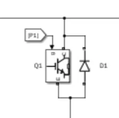
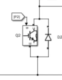
In this, there is four bipolar junction transistors are being used as shown below and this is being controlled
by another circuit. At a time two opposite transistors are in one position and two opposite transistors are
turned off.
 .
.  .
. 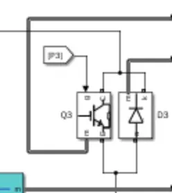
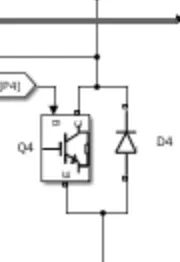
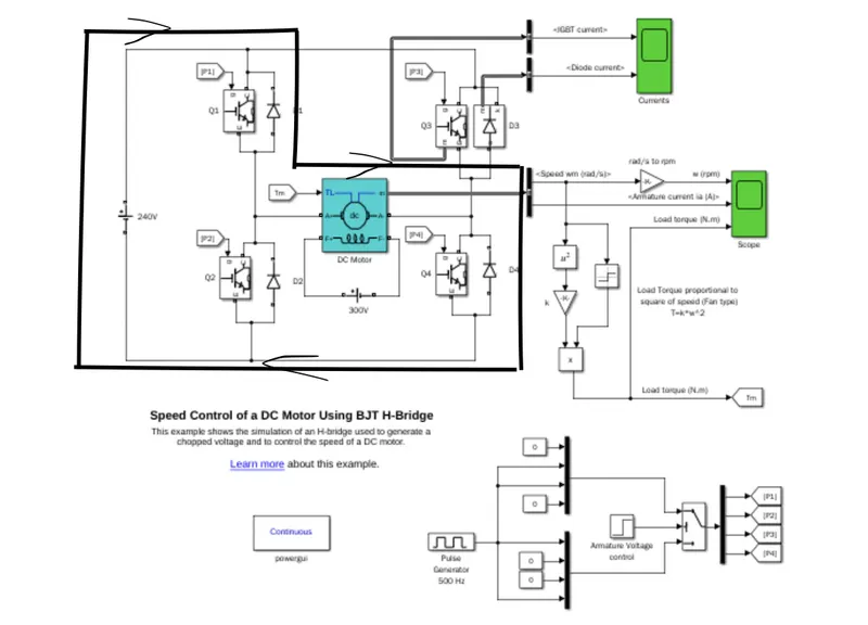
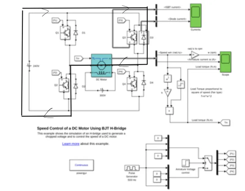
These are two conditions when this transistor is being on
This one is for one direction of rotation or a positive cycle
This is for the opposite direction of rotation or negative cycle
so with this, we are getting a four-quadrant operation
And also we can control the output power by controlling the base input of the transistor.
Here diodes are used to conduct when suddenly BJT gets turned off and due to induction
present in the motor current cannot be zero suddenly then these diodes are conducting.
Powerful-
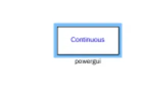
This uses a variable-step solver to solve Simpower blocks. This is shown below.
Separately excited motor-
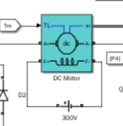
This is a DC motor which is having a field winding excited by a separately Dc supply
as shown below
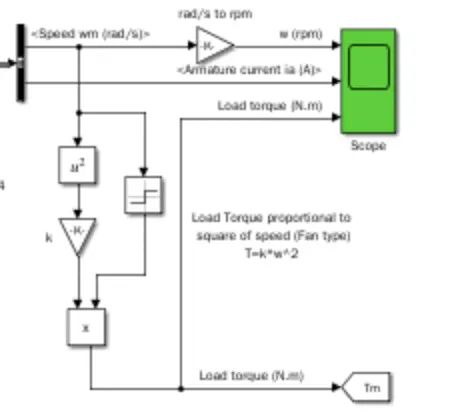
Measurement of speed and torque and feedback back to the DC motor and scope is used to
show torque and speed and armature current as shown below
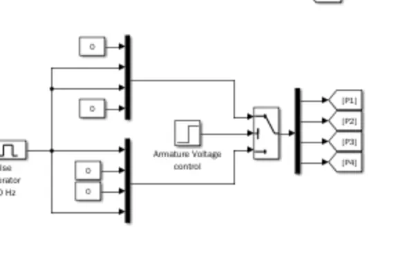
Control circuit-
This is the main controller for the DC motor which makes and transistor turned on or off
as we want we will send a signal to the base of the transistor so that the transistor should be in
situation region and supply power to the motor
Below is the circuit for speed control of a DC motor using BJT.
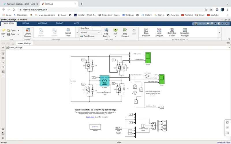
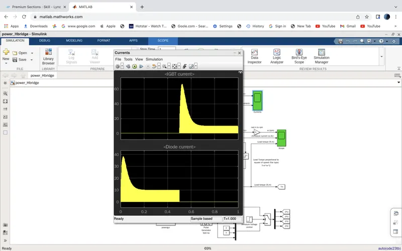
I have paste 'power_Hbridge' in the command in the command section and press enter.
And I have got the result in scope which we can observe by double click on the scope
Output
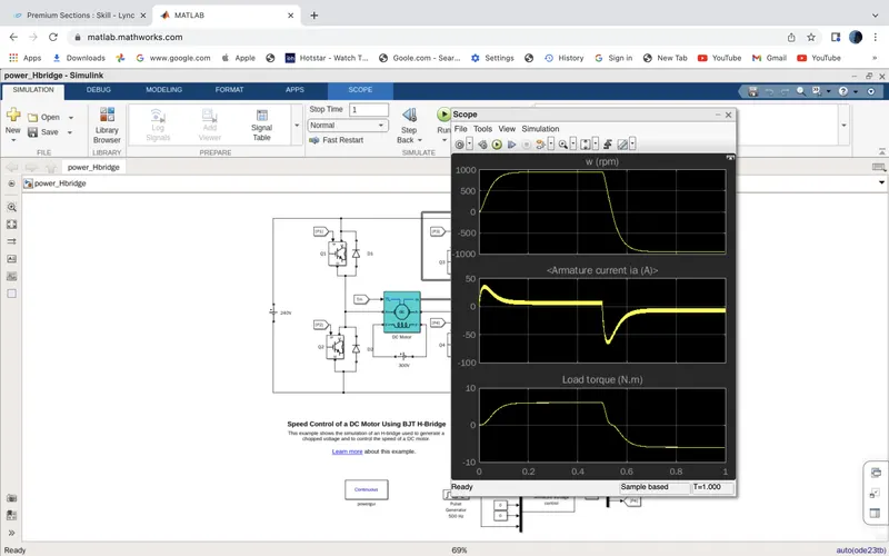
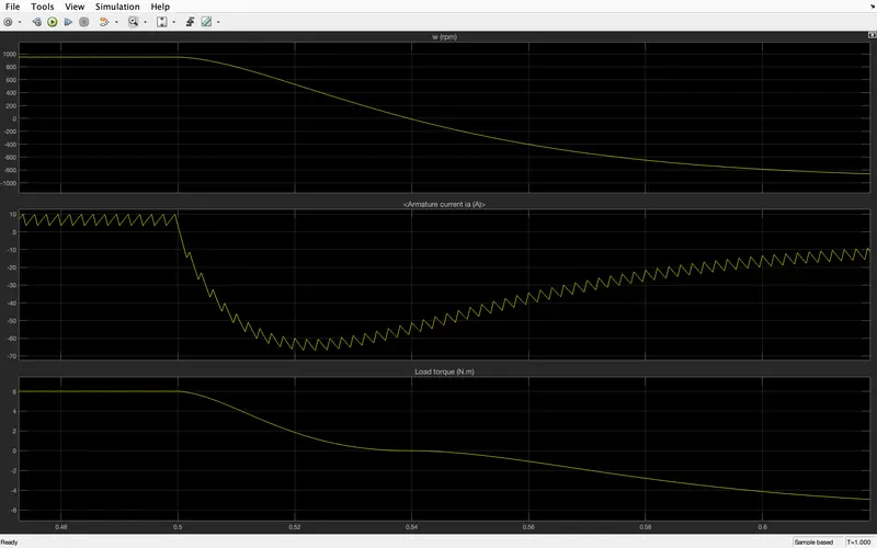
Below are the output speed, armature current and load torque characteristics
observe.
B)
the armature's current shoot-up from the scope results-
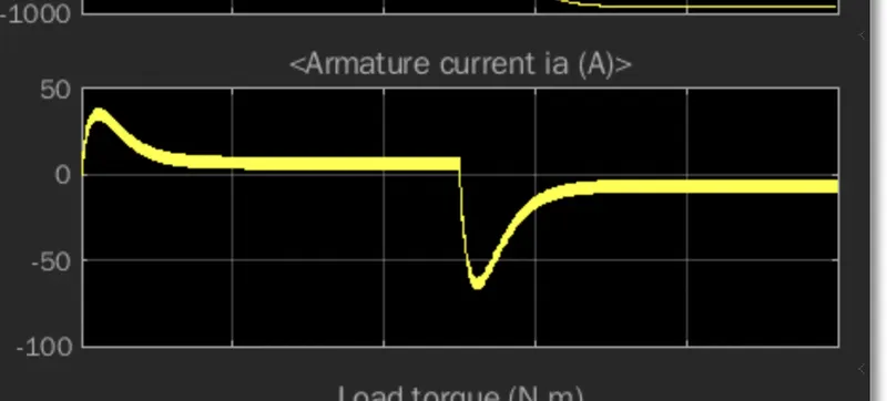
when we will zoom this we will get the below result in it and it is due to ripple content present
in the input supply. We are not getting pure dc input to the armature

At the starting when the motor is stopped and we are applying power to the motor then due zero
back emf present in the motor current flowing in the armature will be maximum and torque
also will be maximum. But as back emf start raising current slowing down when speed
reaches to maximum then current became very less now when the input supply cut off
then due to the field present (sapraitly excited motor) motor will start behaving as a generator
and opposite current will start flowing in the armature.
The Four-Quadrant Chopper DC Drive (DC7) block-
we have pasted this 'dc7_example' command in the command section and pressed enter.
then we have to get a four-quadrant chopper dc drive block as shown below
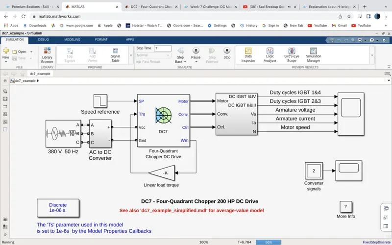
after running this model we have gotten the duty cycle of IGBT 1,4 and IGBT 2,3 and armature voltage, armature
current and motor speed graph as shown below
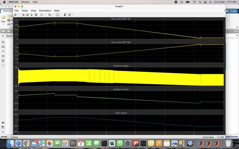
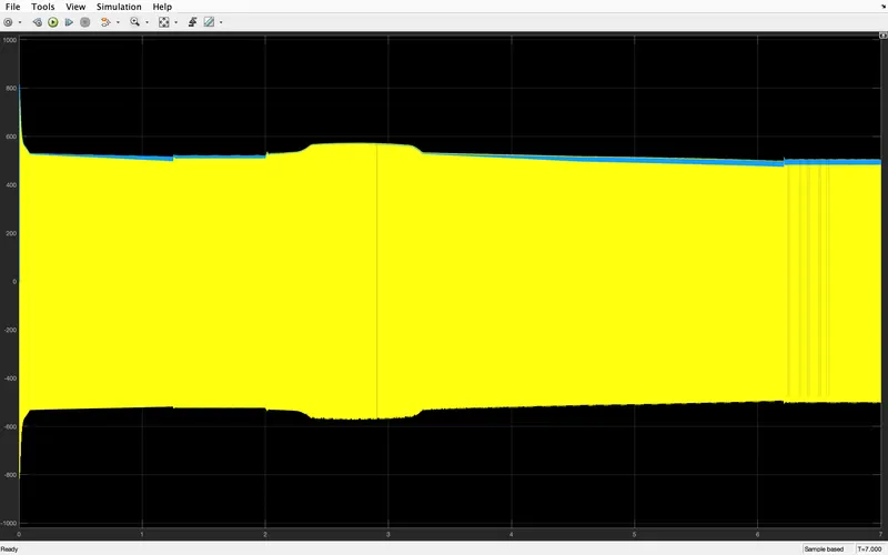
after zooming the armature voltage we have got the below graph
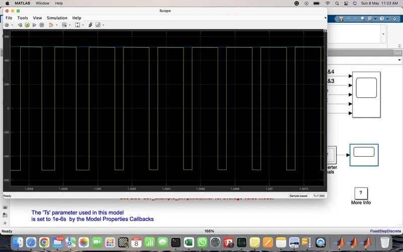
we have used the below signal for the converter signal
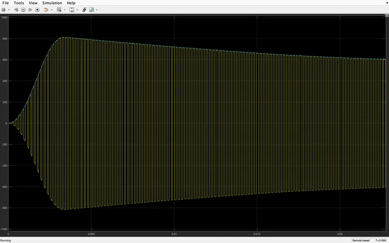
below is the converter signal after zooming
C)
comparison between H-bridge using BJT vs DC7 four-quadrant chopper in speed control of DC motor
H-bridge based DC7 four-quadrant chopper based
1 In this time two-transistor or two thyristors Here also at a time two-thyristor will in conduction
are in conduction mode and two of them will be mode two of them will be in the off state
in off state
2 Two quadrant operations possible in this Four quadrant operations are possible in this
device
3. It is a closed-loop system means there It is an open-loop system no feedback path will be
will be one feedback path present in it present in it
4. continuous signal will be present in it Descreat signal will be present in it
5. Ripple content will be more in this device. Ripple content will be less in this device
6 More harmonics will be present in this Less Harmonics will be present in this
device
Ans 2-
2-Quadrant Chopper
Aim-
Build a two-quadrant chopper using Simulink & explain the working of the same chopper.
Software used-
Matlab Simulink
Blocks used to build the model-
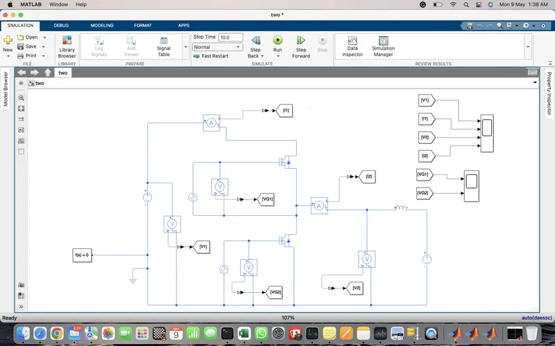
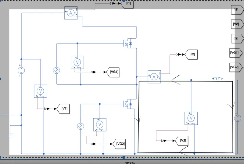
MOSFET, Battery, inductor, goto block, from the block, current sensor, voltage sensor,
scope, solver configuration and electrical reference
Below Picture is the Matlab model for 2 quadrant chopper
Theory-
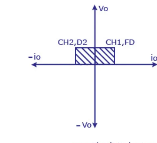
This chopper is 2 quadrant chopper because in this voltage is but the current is positive as well as negative
so it will cover two-quadrant because of that we will call it as 2 quadrant chopper
below is the operation quadrant of the chopper
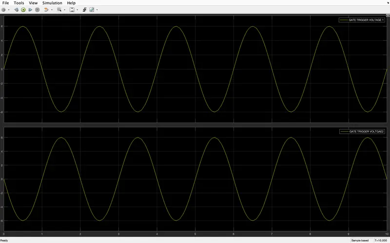
Both MOSFETs cannot be turned on due to a short battery circuit, so we will
use 180 phase difference between two gate signals. below is the gate signal used to turn
on the MOSFET we can see from this figure that for the N-channel of MOSFET both the MOSFET
cannot turn at the same time due to the 180-degree phase difference of the gate signal
1) when MOSFET first is on, Then below is the current path
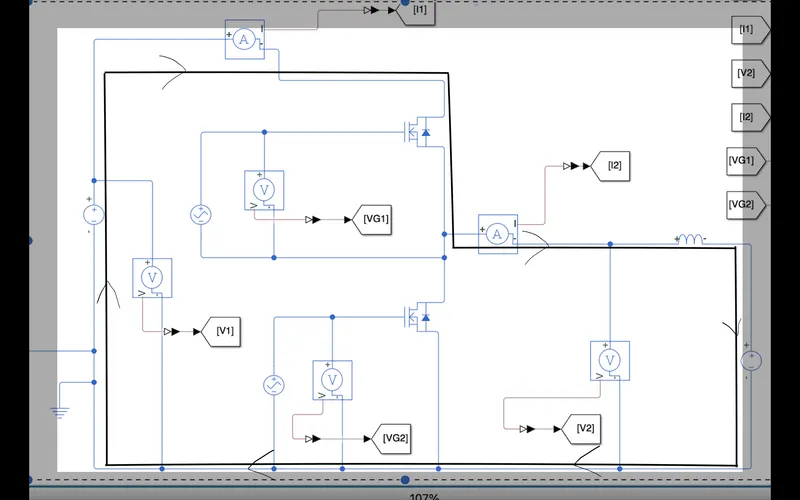
when MOSFET2 is on, then below is the current path
Output-
Below is the output of the 2- quadrant chopper
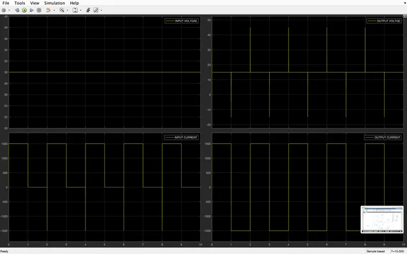
positive half-cycle current is due to 1 MOSFET and the negative cycle is due to the 2 MOSFET turn on.
Brushless DC motor-
Brushless DC motors are a little bit different than brushed motors because as the name implies brushless
DC motor does not have a brush. That means there is no coil present on the rotor side. In this motor
permanent magnets are used to produce the magnetic field, rotor only will have coils which are fed by a
dc supply, In this motor, we can control the speed and torque by varying the input voltage. For the reverse
direction motion, we need to change the voltage terminal from negative to positive
In this motor, all stationary parts only have flowing electricity and the rotor part is just having a permanent
magnet. So in this type of motor commutator is not required.
When we are giving input supply to the stator then stator currents will start producing a magnetic field and
this magnetic field will interact with the rotor permanent magnet which will cause the rotation of the motor