Project
System-level simulation of an all-terrain vehicle
Aim-
A technical report on the Baja model of an all-terrain vehicle and preparing a technical report explaining the model properties and comments on the result.
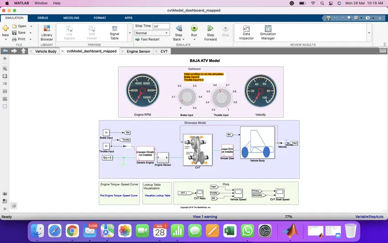
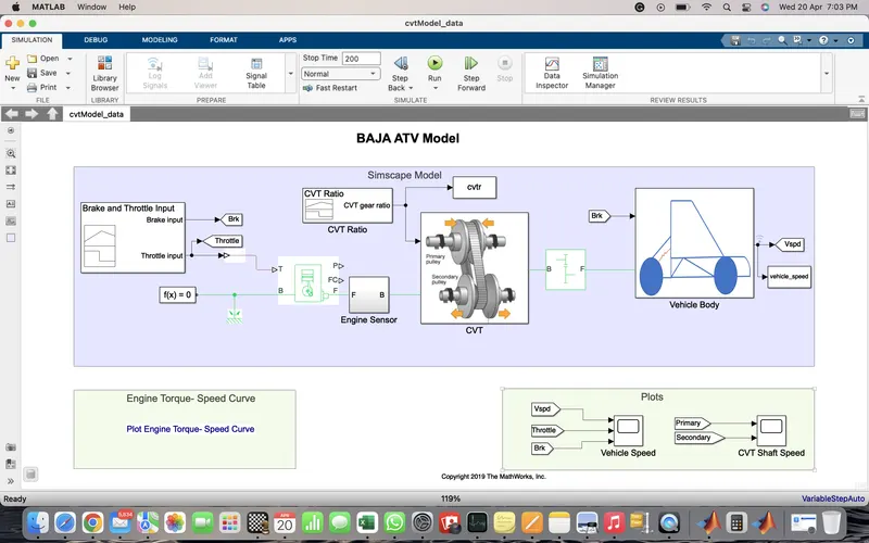
Block diagram picture of Baja ATV model-
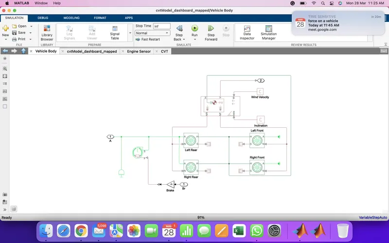
vehicle body Matlab block diagram picture
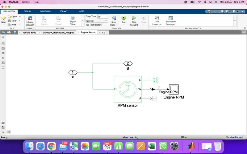
Engine speed sensor Matlab model block diagram picture
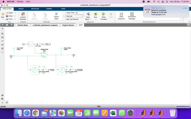
CVT block diagram Matlab picture
Required elements-
Baja ATV model is made up of three subsystems-
(1)- Engine sensor
(i)-Ideal rotational motion sensor (II)- physical terminator. (III)-physical to Simulink converter (IV)-scope
(2)- continuously variable transmission
(I)-inertia (II)-Ideal rotational motion sensor (III)-variable-ratio gear (IV)-ps lookup table (V) ps to Simulink
converter (VI) goto block (VII) ps terminator (VIII)
(3)-Vehicle body
(I) inertia (II) double shoe brake (III) Tire (IV) gain (V) from (VI) ps terminator (VII) vehicle body
(VIII) physical constant
other parts
(I) circular gauge (II) knob (III) generic engine (IV) simple gear (V) mechanical rotational reference (VI) constant (VII) solver configuration (VIII) goto (IX) simulation data inspector (x) from block (XI) scope
Theory-
This is a real model data used in Matlab taken by the Baja model. Here lookup table data is taken by the real values.
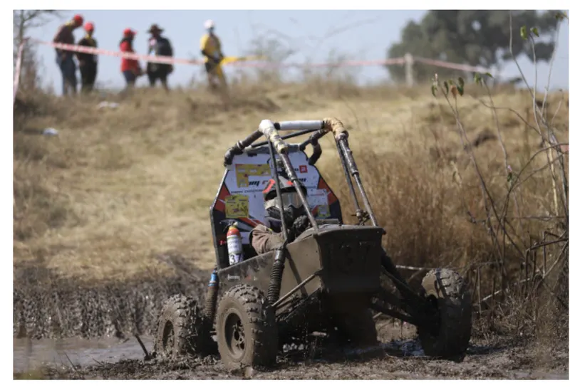
This is an off-road vehicle this is run by SAE (Society of automotive engineers international). This type of vehicle is maximumly used for mountain areas.
some important elements-
(i)Generic engine-
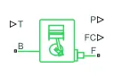
This is a fuel-operated engine. This is converting energy into a mechanical system and then the vehicle starts rolling.
(II) vehicle body
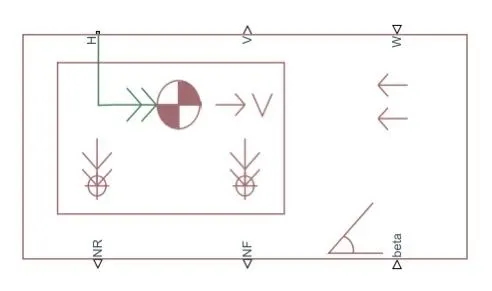
This is a two axel vehicle body. Beta is a slope of the road on which a vehicle is running. W is a wind flow faced by vehicles while running. H is the center of weight for the vehicle. NR is rear axel normal force and NF is front axel normal force. V is the longitudinal velocity of the vehicle.
Knob
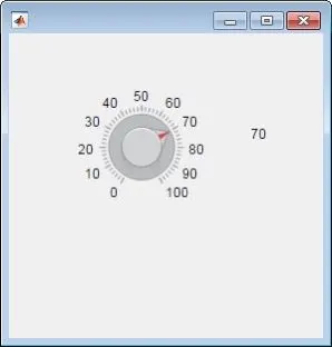
This is used as an input device which we can vary while running by changing the knob value.
circular gauge
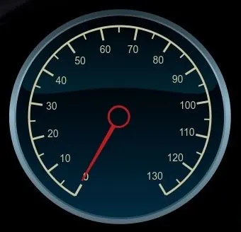
circular guage we can use for the measuring of any variable which is varying or constant does not matter we can measure every value while running the program.
Variable transmission ratio

This is used for the transmission of torque and velocity to the base and the follower.
Ideal rotational motion sensor

This is used to measure the vehicle's rotational speed.
double shoe brake
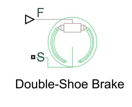
This is used to stop the rotating part of any vehicle or axel.
Tire

This is used for the running of the vehicle which is attached to the axel.
Procedure to make the vehicle in Matlab
(i) We have taken a generic engine that is connected through a knob by using a constant block. We have connected one solve configuration to a generic engine and we have used one rotational sensor for its output speed measurement.
(ii) The torque produced in a generic engine is given to the variable ratio transmission which is transferring the torque to the simple gear mechanism that is connected to the axel of the vehicle body.
(iii) Between axel and gear we have used a double shoe brake to control the vehicle which is connected to knob through goto and from the block as shown in the above figure.
(iv) I have used a three-speed sensor first one for engine speed two for output and input of the variable-ratio transmission and all these three sensors are connected to a scope by using goto and from function.
(v) I have used two circular gauges for engine speed one for output speed measurement.
(vi) I have taken feedback from the output and feedback to the lookup table and that lookup table is connected to the variable transmission ratio. In the lookup table, we have used pretty much realistic data.
(vii) I have connected physical constant to vehicle beta(road incline angle) input and air drag.
(viii) I have connected all H of the tire and connected to h of the vehicle body.
(ix) I have connected the rear of to rare normal force tire and front to the front as shown.
(x) I have connected many inertia blocks to a different part of the vehicle which is representing the weight of the different types of equipment
(xi) all the values we have to get on the scope and we have used from the block for every goto block.
output-
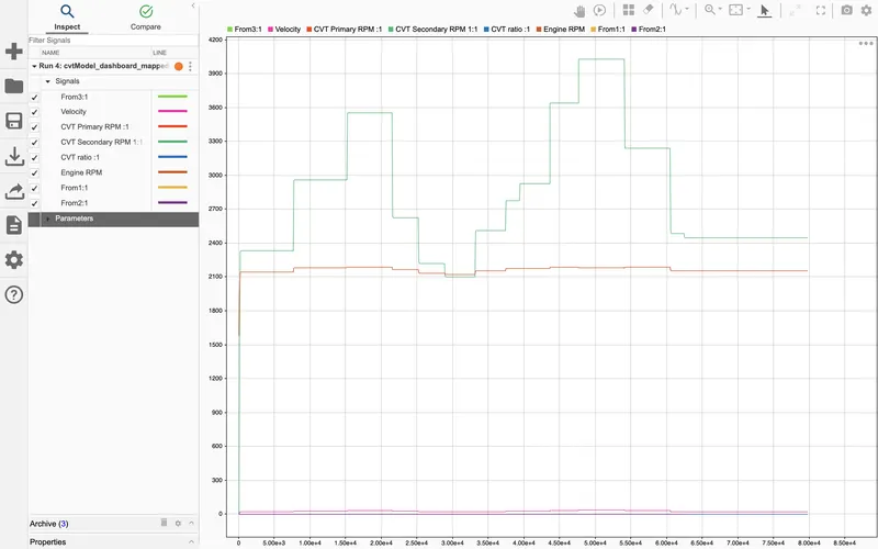
as the graph we can observe that when we are increasing throttle input we see that the velocity of the
vehicle also increases and when we are applying some brake along with throttle we are seeing fewer changes on
velocity of the vehicle
(2)Given input for brake and throttle as fixed as shown below and 1-D table used as input to the variable transmission ratio shown-
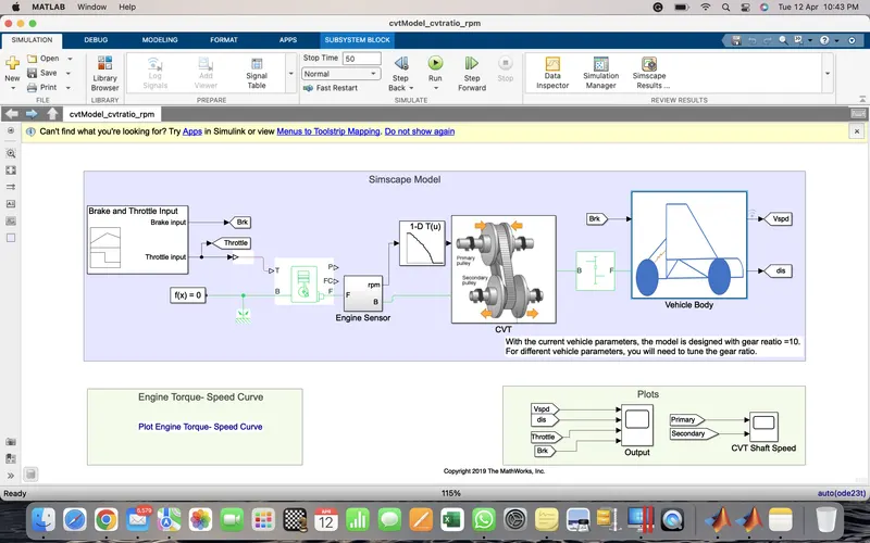
Output-
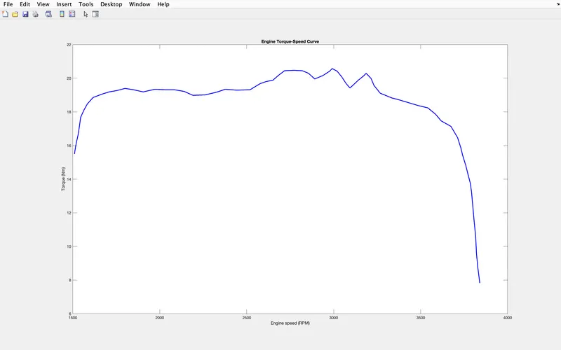
- At the starting speed of the vehicle is increases slower than the torque but after some time torque became constant
and speed is keep on increasing after some time torque is reducing very fast and speed is increasing very slowly as
shown above
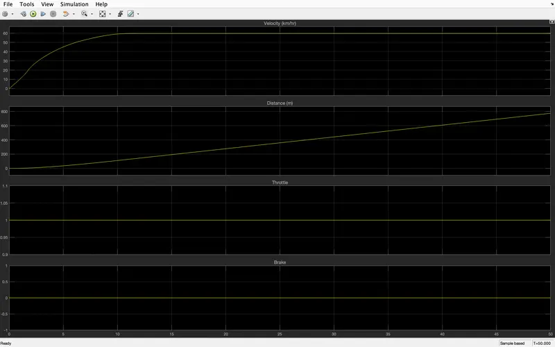
Here when we are applying constant input to throttle then the velocity starts increasing and after 12 seconds it's become constant
since brake input is zero here so speed of the vehicle will be constant till we don't change the throttle input
\ 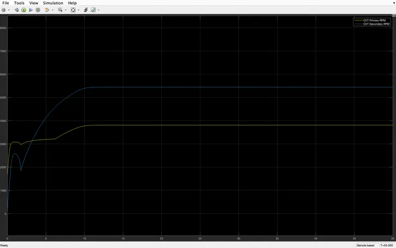
It's the speed graph for input of cvt and output of the CVT and that is shown above
(3) Here step function is used as an input for brake and throttle as shown below
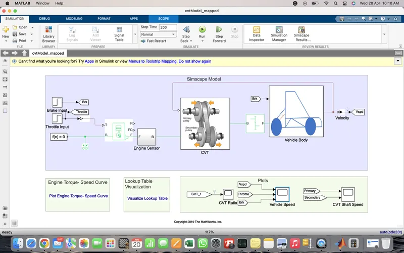
output
At the starting speed of the vehicle is increases slower than the torque but after some time torque became constant
and speed is keep on increasing after some time torque is reducing very fast and speed is increasing very slowly as
shown above
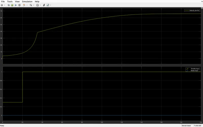
Since here brake input is zero as we applied step throttle input we have seen the speed start increasing
till it is not being constant as shown
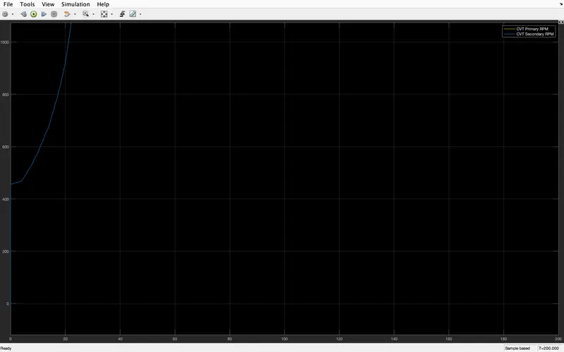
It's the graph of input and output speed of CVT as shown
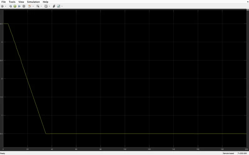
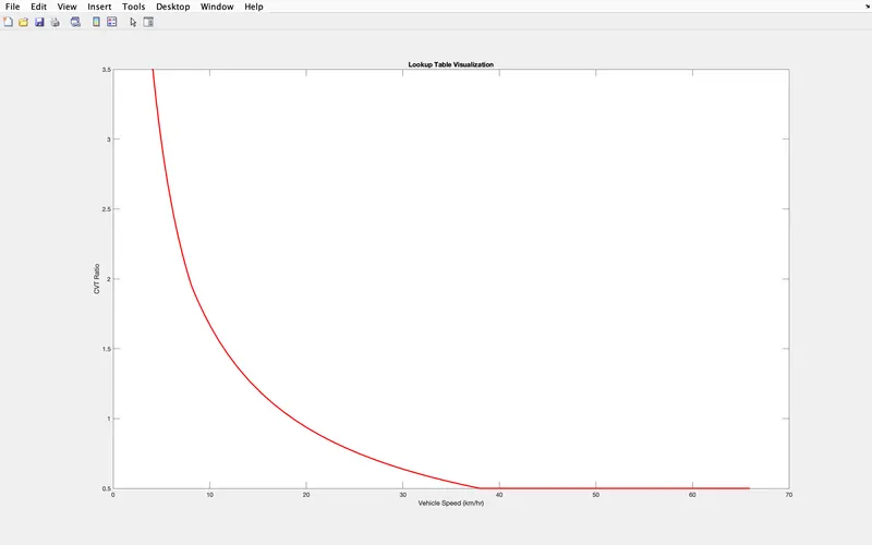
(4) Here we have used a signal generator block for brake and throttle input and also we have used a signal builder for CVT
as shown below
output
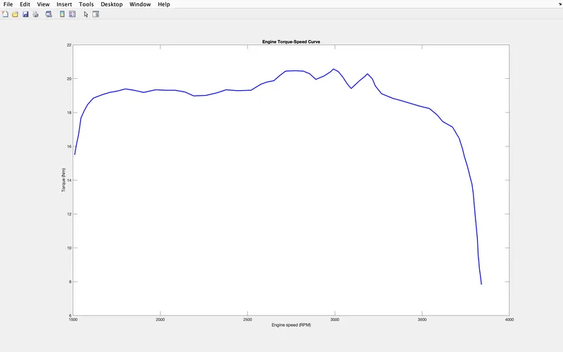
The starting speed of the vehicle is increases slower than the torque but after some time torque became constant
and speed keeps on increasing after some time torque is reducing very fast and speed is increasing very slowly as
shown above
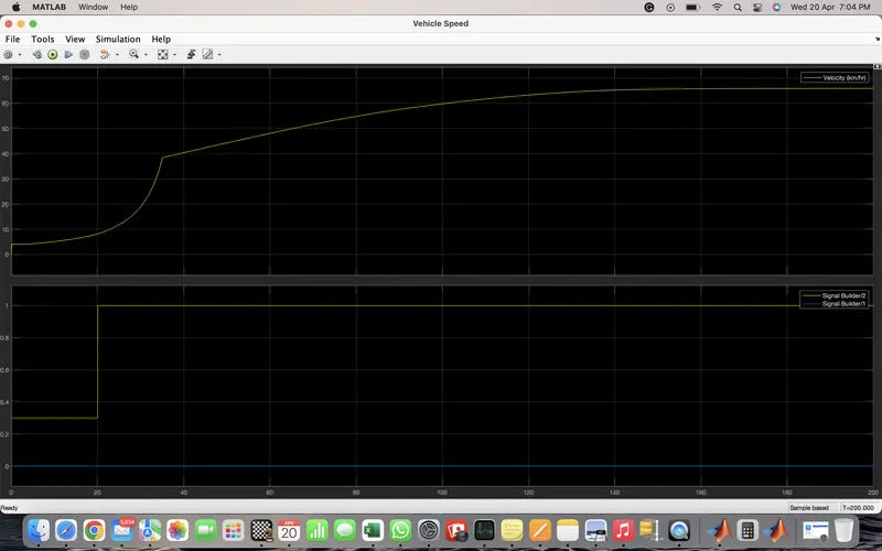
Since here brake input is zero as we applied step throttle input we have seen the speed start increasing
till it is not being constant as shown
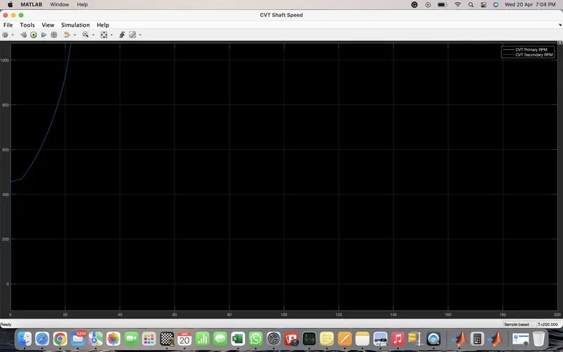
It's the graph of input and output speed of CVT as shown