Week -2
Ans 1
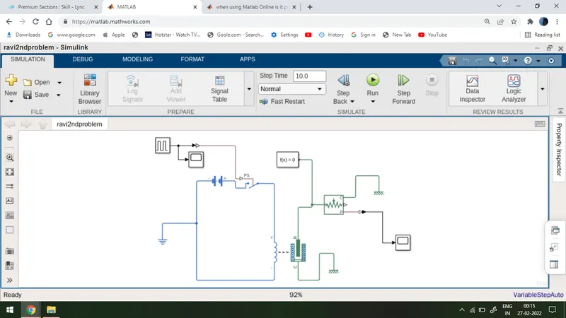
A Simulink model of Doorbell using solenoid block
Block diagram picture
Elements required
Pulse generator, scope, battery, Simulink to the physical converter, switch, solenoid, electrical reference, motion sensor, solver configuration, translational reference, physical to Simulink converter
Procedure
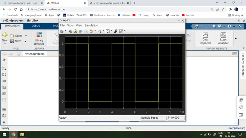
1 I have taken pulse generator and I have changed the on period and off period as 2,2.
2 I made a circuit with a battery, switch, solenoid and electrical reference as shown in the picture.
3 I have just connected the switch with the pulse generator.
4 I have completed the mechanical part of a circuit with a motion sensor and solver configuration. The position sensor is connected with the scope as shown in the picture.
5 Translational reference is connected with solenoid and motion sensor
6 I have given stop time as 10 seconds and I have run the program.
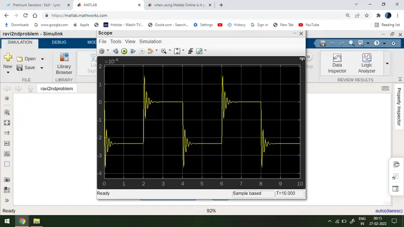
Output
we have got the output result as shown in the picture.
Input waveform picture
Ans 2
Thermistor to sense the temperature of a heater & turn on or turn off the fan as per the below conditions
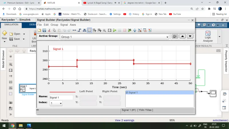
Temperature source: 20 °C from 0 to 10 seconds, 27 °C from 10 to 30 seconds, 23 °C from 30 to 50 seconds
Fan conditions: ON if the temperature above 25 °C, OFF otherwise
Block diagram picture
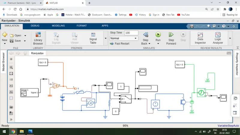
Elements required
Signal builder, Simulink to the physical converter, controlled temperature source, solver configuration, thermister, battery, voltage sensor, resistance, electrical reference, physical to Simulink converter, scope, switch, constant block, display, controlled voltage source, dc motor, rotational reference
procedure
1 I have changed the degree to Kelin and used signal builder block to generate the required input waveform.
2 I have used a controlled temperature source to generate a given temperature as shown in the picture.
3 I have made a circuit with a thermistor resistance and voltage sensor as shown.
4 I have used conditional switch and given threshold voltage ( i have taken threshold voltage by applying 298.15-kelvin temperature).
5 Output of switch is connected to display and scope as well as to control voltage source.
6 I have made a circuit with a controlled voltage source and dc motor as shown.
7 Motor is connected with a rotational motion sensor as shown and that is connected to the scope by physical to Simulink converter.
8 I have given stope time as 100 and I have run the program.
Result
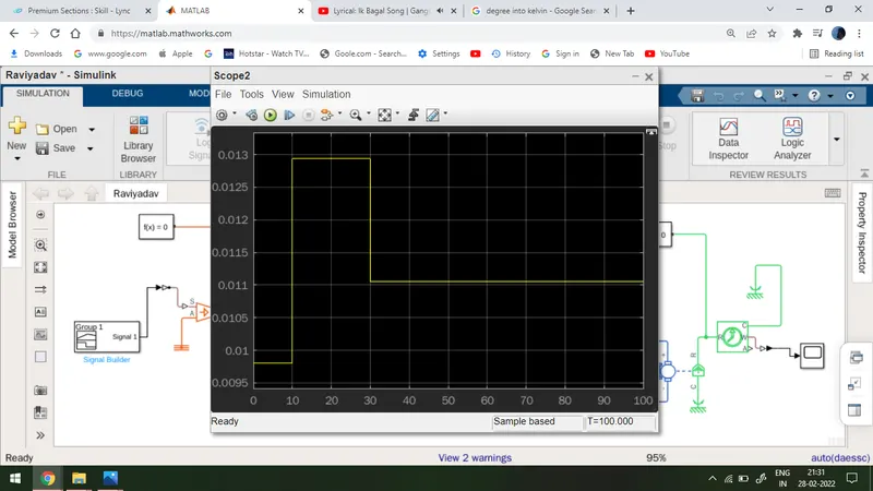
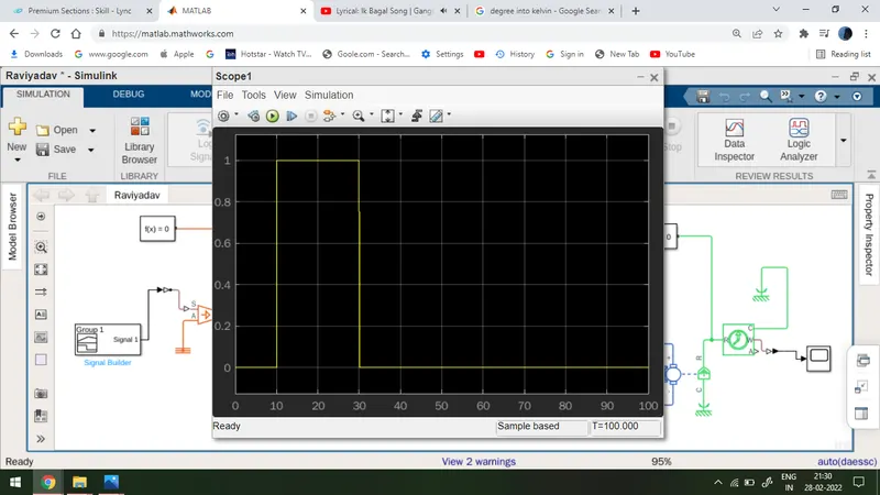
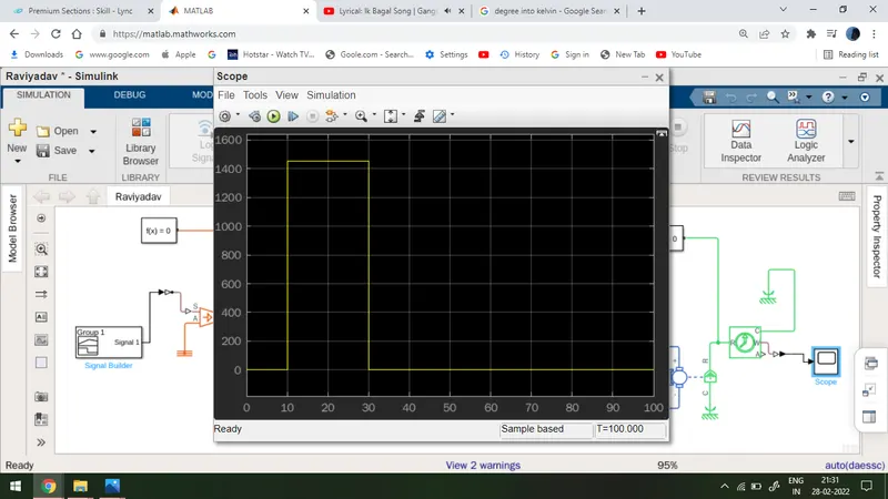
THE OUTPUT OF THE GIVEN PROBLEM IS SHOWN IN BELOW:-
output of a voltage sensor
The output of a switch
The outp
ut of a motion sensor
Input waveform