Week - 4
Ans1
Aim- Implementation and control logic of a “washing machine” using Stateflow as per given sequence:
- If the power supply is available, the system gets activated
- If the Water supply is not available, stop the process & indicate through LED
- Soaking time should be 200s followed by Washing time of 100s.
- Then rinsing happens for next 20s & dryer runs for 50s
- After all the processes have been completed turn on the finished LED
Required elements-
1 Constant block, Stateflow chart, display, lamp
Block diagram picture of washing machine-
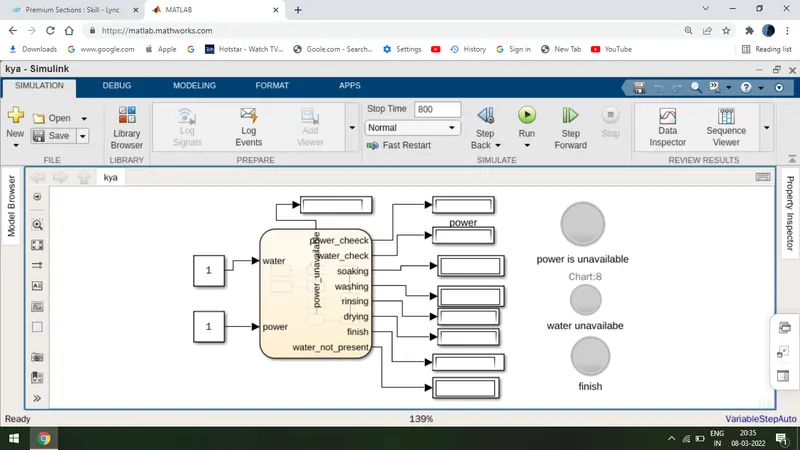
procedure-
1 Take a Stateflow chart and open it after opening take 8 states and connect them as shown in the above figure
2 I have implemented all the conditions as shown in the picture as
(i) power present or not
(ii) water present or not
(iii) I have given the 200-sec delay in soaking.
(iv) I have given a 100-sec delay in washing.
(v) I have given a 20-sec delay in rinsing.
(vi) I have given a 50-sec delay in drying.
3 I have made input sections as water and power and output section as
power_check, water check, soaking, washing, rinsing, drying, finish, water not present, power not available.
4 I have given run time as 800 sec.
5 I have saved the program.
6 I have the program
Result-
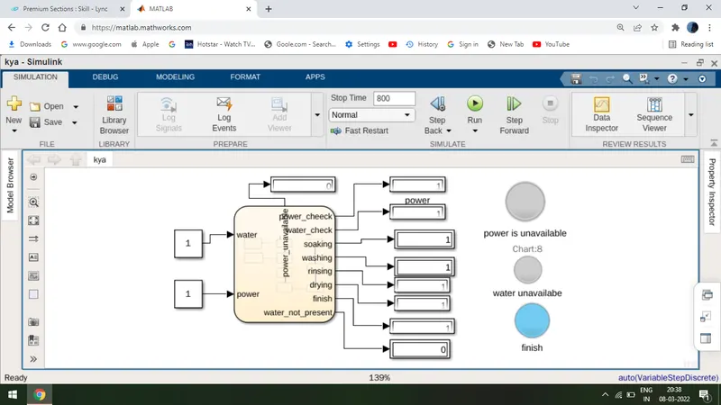
Implemented the control logic of a “washing machine” using Stateflow as per given condition I have got the proper sequence of output as
(i)power check, (ii)water check, (iii)soaking dealy till 200-sec, (iv)washing till 100-sec, (v)rinsing till 20-sec, and then (vi)finish.
output result screenshot
Ans 2
Aim- Implementation of Simulink chart for the “Gear shift” logic as per below conditions:
Speed Range(km) Gear
0 to 15 1
16 to 25 2
26 to 40 3
41 to 60 4
Above 61 5
and display it to the screen.
Required elements-
1 constant block, slider gain, Stateflow chart, display
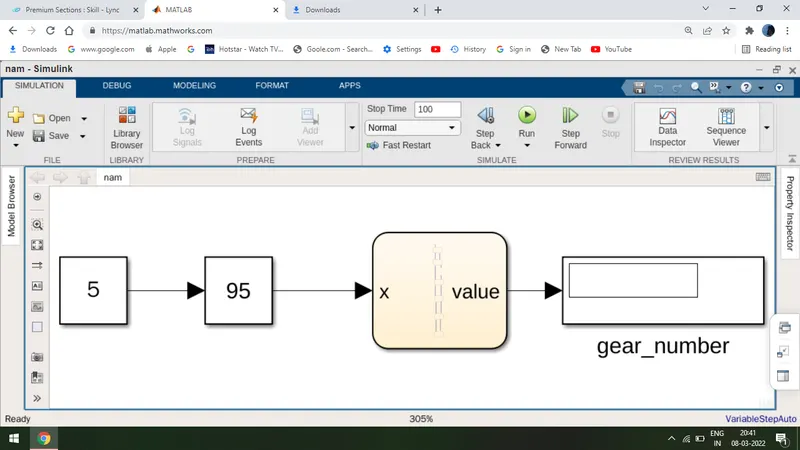
Block diagram picture-
procedure-
1 Take a Stateflow chart that takes 6 states and connect them as shown in the picture. Name as
1 start
2 gear1=1
3 gear2=2
4 gear3=3
5 gear4=4
6 gear5=5
2 keep the first state name as a start, the second state as gear one and give conditions as x>0 for outflow and x<0 for inflow.
3 Second state is connected to the third state and give the condition as x>15 for outflow and x<15 for inflow.
4 Third state is connected to the fourth state and give the condition as x>40 for outflow and x<40 for inflow.
5 Fourth state is connected to the fifth state and give condition as x>60 for outflow and x<60 for inflow.
6 Connect a constant block to the input x through slider gain.
7 Connect a display to an output of Stateflow value, as shown in the above picture.
Result-
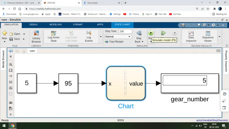
I have got the output gear changed as speed x is being changed while using slider gain.
when x= 27 we got the gear=3
when x=63 we got the gear=5
as continue.