Week-7 Challenge: DC Motor Control
Q.1.
DC MOTOR:
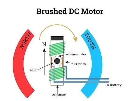
A DC motor or direct current motor is an electrical machine that transforms electrical energy into mechanical energy by creating a magnetic field that is powered by direct current. When a DC motor is powered, a magnetic field is created in its stator. The field attracts and repels magnets on the rotor; this causes the rotor to rotate. To keep the rotor continually rotating, the commutator that is attached to brushes connected to the power source supply current to the motors wire windings.
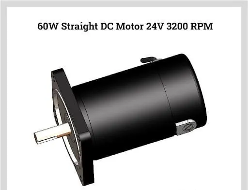
The DC motors are the most preferred motors due to their ability to precision control their speed, which is a necessity for industrial machinery. DC motors can immediately start, stop, and reverse—an essential factor for controlling the operation of production equipment.
Types of DC motors:
- Since DC motors are everywhere and used for a wide variety of applications, there is a different type to meet the needs of every application. Regardless of your need for DC motors, it is important to understand each type since they can be found in every aspect of life.
- DC motors are differentiated by the connections between the field winding and the armature. The field winding can be connected parallel to the armature or connected in a series. In some cases, the connection is both parallel and in a series.
- A further distinction of DC motors is how the rotor is powered; it can be brushed or brushless. In brush DC motors, the current is applied to the rotor by brushes. In a brushless DC motor, the rotor has a permanent magnet.
1. Brushed DC motors:
The magnetic field in a brush DC motor is produced by current sent through a commutator and brush that are connected to the rotor. Brushes are made of carbon and can be separately excited or self-excited. The stator is the enclosure that contains the components of the motor and contains the magnetic field. The winding of the coil on the rotor can be in a series or parallel to form either a series wound DC motor or shunt wound DC motor.
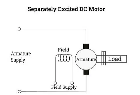
a. Separately excited DC motor:
In a separately excited DC motor, the motor has separate electrical supplies for the armature winding and field winding, which are electrically separate from each other. The operations of the armature current and field current do not interfere with each other‘s actions, but the input power is their total sum.
b. Parmanent magnet DC motor:
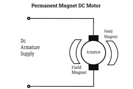
A permanent magnet DC motor has an armature winding but does not have a field winding. The permanent magnet is mounted on the inner surface of the stator core to produce the magnetic field. It has a regular armature consisting of a commutator and brushes.
Permanent magnet DC motors are smaller and less expensive. They use rare earth magnets such as samarium cobalt or neodymium iron boron.
c. Self excited DC motors:
In self-excited DC motors, the field and armature windings are connected and have a single supply source. The connections are parallel or series with parallel made as shunt-wound while the series version is series wound.
Shunt
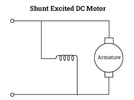
In a shunt wound DC motor, the field and armature windings are connected parallel to each other; this exposes the field winding to terminal voltage. Though the supply is the same, the current for the field and armature windings is different. The speed of a Shunt DC motor is constant and does not deviate with varying mechanical loads.
Series
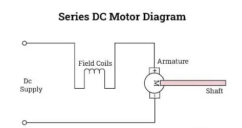
The field and armature winding on a series DC motor are connected to the power supply in a series. The same current flows in the field and armature windings. A series-wound motor can work with AC and DC voltage supply, which makes it a universal motor. Series motors always rotate in the same direction regardless of the voltage source. Their speed varies with the mechanical load.
Compound
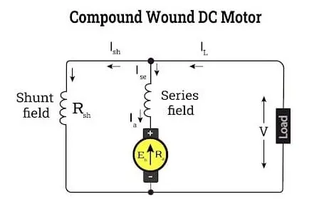
A compound DC motor uses the features of the series and shunt field windings. The winding for the armature is connected in a series while the winding for the field is a shunt or parallel connection.
Compound DC motors are further divided into cumulative and differential. With cumulative DC motors, the flux of the shunt field helps the flux in the series field. They both move in the same direction while the flux of a differential compound DC motor, for the series and shunt fields, moves in the opposite direction. Cumulative and differential compound DC motors can have long or short shunts; this is based on the shunting of the shunt field winding.
2. Brushless DC motors:
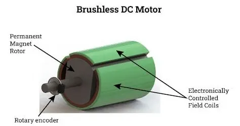
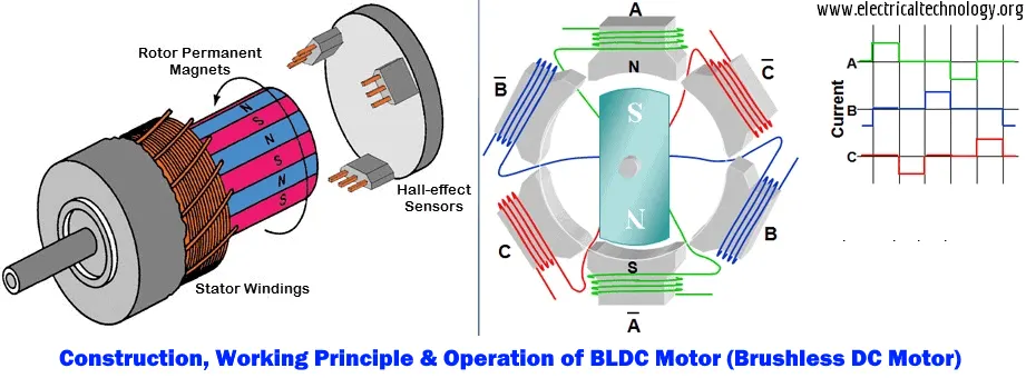
Brushless DC motors have a permanent magnet rotor and a coil wound stator. This design of the DC motor removes the need for brushes. The benefit of a brushless DC motor is the elimination of wear and tear of brushes since very little heat is produced by the rotating magnet. The efficiency of brushless DC motors makes them more expensive.
3. Servo DC motors:
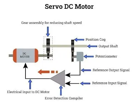
A servo DC motor has four parts: a DC motor, gearbox, control circuit, and position sensing unit. The gearbox changes high-speed input into slower practical speed. The control circuit is an error detector amplifier. The position of the shaft gives feedback to the control circuit and is in a closed-loop. With a servo DC motor, if there is any mismatch between the current position of the shaft and its reference position, an error signal is sent to the error detecting amplifier.
A.
BJT: A bipolar junction transistor is a three-terminal semiconductor device that consists of two p-n junctions which can amplify or magnify a signal. It is a current controlled device. The three terminals of the BJT are the base, the collector, and the emitter.
(BJT) when used for power switching applications, operates as an IGBT. When it is conducting (BJT operating in the saturated region), a forward voltage Vf is developed between collector and emitter (in the range of 1 V). Therefore, the IGBT block can be used to model the BJT device.
The IGBT block does not simulate the gate current controlling the BJT or IGBT. The switch is controlled by a Simulink signal. The DC motor uses the preset model (5 HP 24V 1750 rpm). It simulates a fan type load (where Load torque is proportional to the square of speed). The armature means voltage can be varied from 0 to 240 V when the duty cycle (specified in the Pulse Generator block) is varied from 0 to 100%.
H bridge:
The H-bridge consists of four BJT/Diode pairs (BJT simulated by IGBT models). Two transistors are switched simultaneously: Q1 and Q4 or Q2 and Q3. When Q1 and Q4 are fired, a positive voltage is applied to the motor, and diodes D2-D3 operate as free-wheeling diodes when Q1 and Q4 are switched off. When Q2 and Q3 are fired, a negative voltage is applied to the motor, and diodes D1-D4 operate as free-wheeling diodes when Q2 and Q3 are switched off.
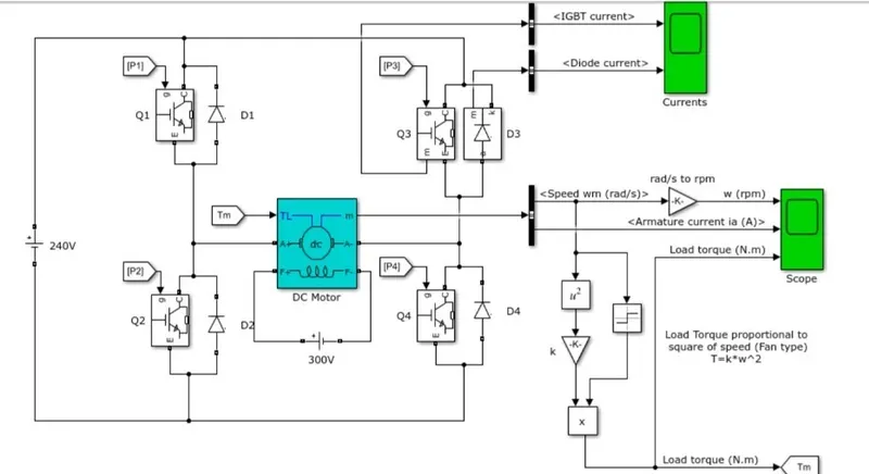
The above-given model is the model that we have to explain i.e., Speed control of a DC motor using BJT H-bridge.
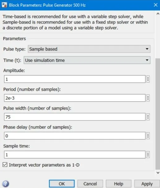
- we have taken the default parameters and the simulation is such that the motor starts rotating in a positive direction with the duty cycle of 75% with a mean voltage of 180V. The scope shows the motor speed, armature current, and load torque. Initially, the block parameters for the pulse generator are as follows
After running the simulation, we get,
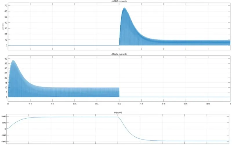
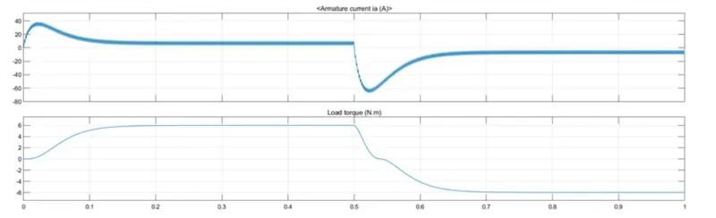
from the result, we can observe that the Ra, i.e. the armature current gets reversed suddenly and the motor runs on the negative side. In the first half, the motor attains 1000 rpm speed and the torque is 6 Nm. In the second half, they go/run in the negative direction with the same values.
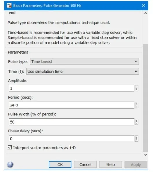
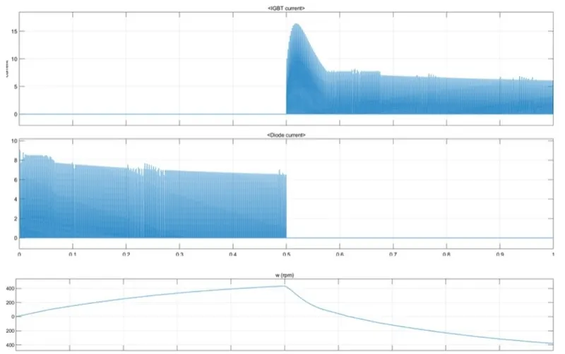
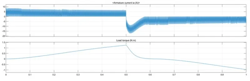
C.2.: the simulation is such that the motor starts rotating in a positive direction with the duty cycle of 50% with a mean voltage of 120V. The scope shows the motor speed, armature current, and load torque. The block parameters for the pulse generator for this case are as follows:
After simulating the C2:
B.
In the result above for the plot of current, we can observe that at 0.5 sec, the armature voltage is suddenly reversed and the motor runs in the negative direction. So, for the 50% duty cycle, in the first half cycle, we can see that motor speed reduced to approx 420 RPM and a load torque of 1.3 Nm respectively. Whereas, for the second half cycle the same values are in the negative direction. Here the armature current of the DC motor does not shoot up at 50%.
From the above observation we get to know that, as we reduce the pulse width (duty cycle), the motor speed and torque reduce and can attain zero whereas when we increase the value of pulse width gradually the speed of the motor and torque also increases gradually to its maximum value.
C.
The 200 HP DC motor is separately excited with a constant 150 V DC field voltage source. The armature voltage is provided by an IGBT converter controlled by two PI regulators. The converter is fed by a 515 V DC bus obtained by rectification of a 380 V AC 50 Hz voltage source. To limit the DC bus voltage during dynamic braking mode, a braking chopper has been added between the diode rectifier and the DC7 block.
The first regulator is a speed regulator, followed by a current regulator. The speed regulator outputs the armature current reference (in p.u.) used by the current controller to obtain the electromagnetic torque needed to reach the desired speed. The speed reference change rate follows acceleration and deceleration ramps to avoid sudden reference changes that could cause armature over-current and destabilize the system. The current regulator controls the armature current by computing the appropriate duty ratios of the 5 kHz pulses of the four IGBT devices (Pulse Width Modulation). For proper system behavior, the instantaneous pulse values of IGBT devices 1 and 4 are opposite to those of IGBT devices 2 and 3. This generates the average armature voltage needed to obtain the desired armature current. To limit the amplitude of the current oscillations, a smoothing inductance is placed in series with the armature circuit.
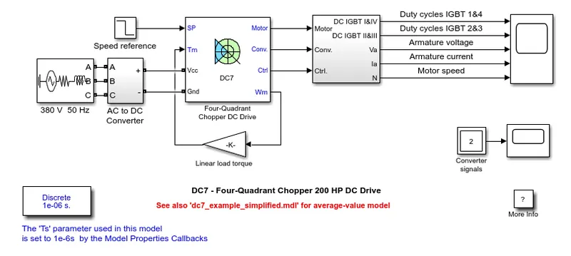
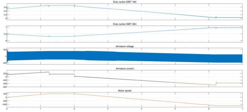
Before starting the simulation, set the initial bus voltage to 515 V via the GUI block ('The Initial States Setting' button and 'Cbus' variable). Start the simulation. You can observe the motor armature voltage and current, the four IGBT pulses, and the motor speed on the scope. The current and speed references are also shown. The motor is coupled to a linear load, which means that the mechanical torque of the load is proportional to the speed. The speed reference is set at 500 rpm at t = 0 s. Observe that the motor speed follows the reference ramp accurately (+400 rpm/s) and reaches steady-state around t = 1.3 s. The armature current follows the current reference very well, with a fast response time and small ripples. Notice that the current ripple frequency is 5 kHz. At t = 2 s, the speed reference drops to -1184 rpm. The current reference decreases to reduce the electromagnetic torque and causes the motor to decelerate with the help of the load torque. At t = 2.2 s, the current reverses to produce a braking electromagnetic torque (dynamic braking mode). This causes the DC bus voltage to increase. At t = 3.25 s, the motor reaches 0 rpm and the load torque reverses and becomes negative. The negative current now produces an accelerating electromagnetic torque to allow the motor to follow the negative speed ramp (-400 rpm/s). At t = 6.3 s, the speed reaches -1184 rpm and stabilizes around its reference.
RESULT:
- The plot of duty cycles IGBT 1&4 is exactly opposite to that of duty cycles IGBT 2&3 as the pulse width of IGBT devices 1 and 4 are opposite to those of IGBT devices 2 and 3.
- The desired armature current is obtained from the average armature voltage.
- The armature current follows the current reference very well, with a fast response time and small ripples.
Comparison of Four Quadrant Chopper DC Drive(DC7) with BJT H bridge
- In the four-quadrant chopper DC drive model, the speed reference input is used to change the direction of the motor rotation whereas, in the BJT H-bridge model, the polarity is reversed across the terminals of the motor concerning the battery, to change the direction of the motor rotation.
- In a four-quadrant chopper, the speed reference values are changed to control the speed of the motor whereas, in BJT H-bridge the speed of the motor is controlled by varying the with of the pulse in the pulse generator.
- The four-quadrant chopper DC drive operates in four-mode i.e, forward motoring, forward regenerative braking, reverse motoring and reverse regenerative braking whereas, the BJT H- bridge only operates in two modes i.e, forward and reverse.
- PI (Proportional) controllers are used for speed and current control in DC7 and it is absent in BJT H- bridge.
- The four-quadrant chopper uses ramps to avoid current shoot up and smooth working and stability.
- The disturbances and current shoot-up are low in DC7 whereas for BJT the shoot-up is high because of switching losses.
- Due to the high switching frequency in the four-quadrant chopper (DC-DC converters), a low armature current is obtained.
- This is why the overall performance and stability are good in Four Quadrant Chopper DC Drive as compared to BJT H- bridge model.
- The only disadvantage is due to its complexity as it consists of four switching devices.
Q.2.
A chopper is a static device that converts a fixed DC input voltage to a variable DC output voltage. It is a high-speed ON/OFF semiconductor switch. It may be thought of as the DC equivalent of an AC transformer since they behave identically.
Chopper is fed through a constant DC voltage source and its output is variable DC voltage. The average value of output DC voltage may be less than or higher than the input DC voltage source. A simple diagram defining the chopper is shown below.
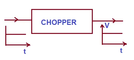
A chopper is a DC equivalent to an AC transformer having a continuously variable turn ratio. Like a transformer, it can be used to step up or step down the fixed DC input voltage. On this basis, there are two types of choppers: Step-up and Step-down Chopper. A chopper whose average value of DC output voltage is more than the fixed DC input voltage is called Step-up Chopper. While a chopper whose average value of DC output voltage is less than the DC input voltage is called a Step-down chopper.
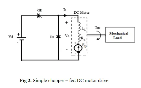
Chopper-Fed DC Motor Drive- D.C motor is considered a SISO (Single Input and Single Output) system having torque/speed characteristics compatible with most mechanical loads. This makes a DC motor controllable over a wide range of speeds by proper adjustment of the terminal voltage
A simple chopper–fed DC motor drive is shown in Fig.2. The basic principle behind DC motor speed control is that the output speed of a DC motor can be varied by controlling armature voltage for speed below and up to rated speed keeping field voltage constant. The armature voltage can be controlled by controlling the duty cycle of the converter (here the converter used is a DC chopper)
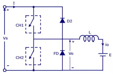
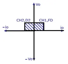
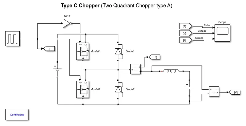
The above model is the model of Type Chopper(Type A Two Quadrant Chopper). In this type of Chopper, the average voltage will be always positive but the average load current might be positive or negative. The two Switches CH1 and CH2 should not be turned on simultaneously as the combined action may cause a short circuit in supply lines. For regenerative braking and motoring, this type of chopper configuration is used.
We will always get a positive output voltage V0 as the freewheeling diode FD is present across the load. When the chopper CH1 is on the current flows from source to load. The inductor stores energy. When Ch1 turns OFF the freewheeling diode starts conducting and the output voltage v0 will be equal to Vs. The direction of the load current i0 will be reversed. The current i0 will be flowing towards the source. The load current will be negative when the CH2 is on. The current completes its path through diode D2.
Q.3.
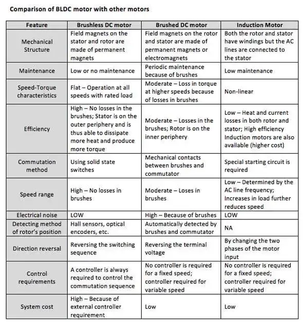
A BLDC or Brushless DC motor is a permanent magnet synchronous electric motor that is driven by direct current and it comprises of electronically controlled commutation system (commutation is the process of producing rotational torque in the motor by changing the phase current through it at an appropriate synch time) instead of mechanical commutation system. BLDC motors are also referred to as trapezoidal magnet motors.
Unlike conventional brushed type DC motor, wherein the brushes make the mechanical contact with a commutator on the rotor so as to form an electrical path between a DC electric source and rotor armature winding, BLDC employs electrical commutation with a permanent magnet rotor and a stator with a sequence of coils. In this motor, generally permanent magnet (or field poles) rotates and current-carrying coil (conductors) are fixed. So, BLDCM is superior to brushed DC motor as it has the ability to operate at high speed, high efficiency, and better dissipation.
They are an indispensable part of modern drive technology, most commonly employed for actuating drives, machine tools, electric propulsion systems, robotics, computer peripherals, and also for electrical power generation.
The layout of a DC brushless motor varies depending on whether it is an 'Outrunner' or 'Inrunner' style.
- Outrunner- In outrunner type BLDCM the field magnet is a drum rotor that rotates around the stator. This style is preferred for applications that require high torque and where the high speed of the motor is not required.
- Inrunner- In inrunner type BLDCM the stator is a fixed drum in which the field magnet rotates inside, inside the rotor. This style is usually preferred for applications that require less torque and are capable of spinning at high speed.
But the basic fundamental principle for both types of BLDC motor is the same. The images for inrunner and outrunner type BLDC motors are given below.
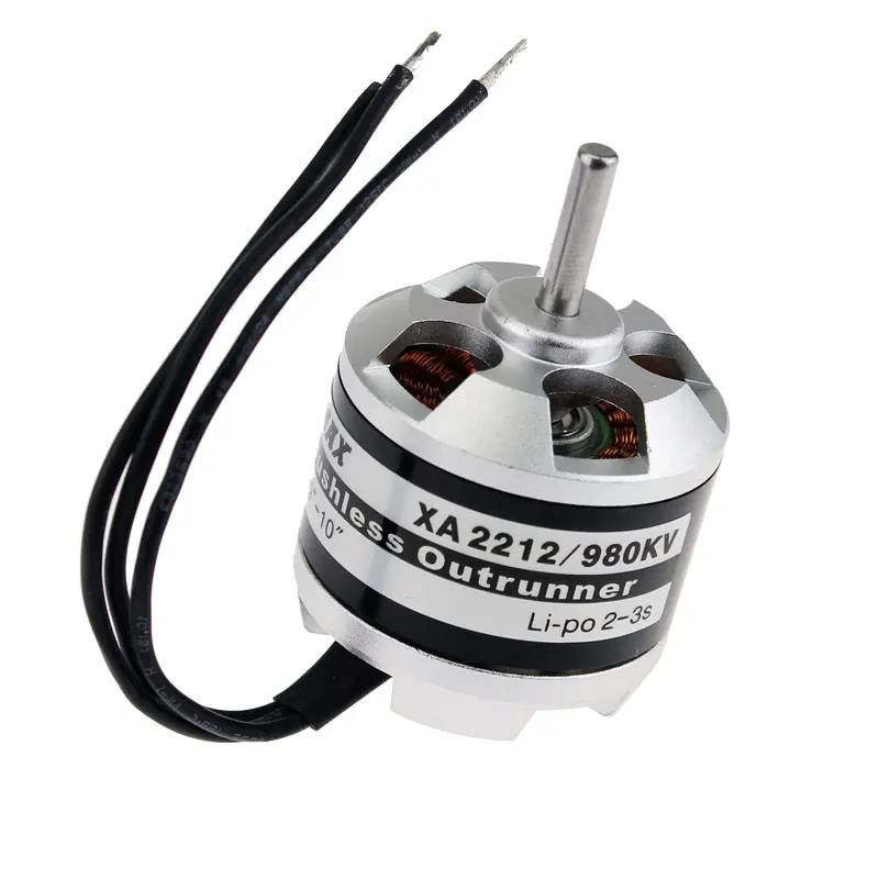
Outrunner BLDC motor Inrunner BLDC motor
BLDC motor works on the principle similar to that of a brushed DC motor which is based on the Lorentz force law which states that whenever a current-carrying conductor is placed in a magnetic field it experiences a force. As a consequence of the reaction force, the magnet will experience an equal and opposite force. In the BLDC motor, the current-carrying conductor is stationary and the permanent magnet is moving.
Construction of BLDC
BLDC motors can be constructed in different physical configurations. Depending on the stator windings, these can be configured as single-phase, two-phase, or three-phase motors. However, three-phase BLDC motors with permanent magnet rotors are most commonly used. The construction of this motor has many similarities to the three-phase induction motor as well as the conventional DC motor. This motor has stator and rotor parts like all other motors.
1. Stator- The stator of a BLDC motor is made up of stacked steel laminations to carry the windings. These windings are placed in slots that are axially cut along the inner periphery of the stator. These windings can be arranged in either star or delta. However, most BLDC motors have a three-phase star-connected stator.
Similar to an Induction AC motor, the BLDC motor stator is made out of laminated steel stacked up to carry the windings. Windings in a stator can be arranged in two patterns; i.e. a star pattern (Y) or delta pattern (∆). The major difference between the two patterns is that the Y pattern gives high torque at low RPM and the ∆ pattern gives low torque at low RPM. This is because, in the ∆ configuration, half of the voltage is applied across the winding that is not driven, thus increasing losses and, in turn, efficiency and torque.
Each winding is constructed with numerous interconnected coils, where one or more coils are placed in each slot. In order to form an even number of poles, each of these windings is distributed over the stator periphery. The stator must be chosen with the correct rating of the voltage depending on the power supply capability. For robotics, automotive, and small actuating applications, 48 V or less voltage BLDC motors are preferred. For industrial applications and automation systems, 100 V or higher rating motors are used.
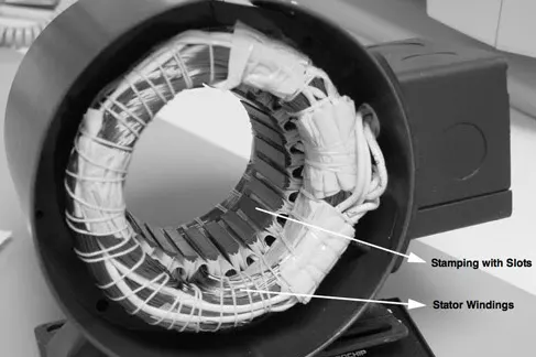
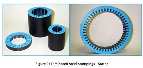
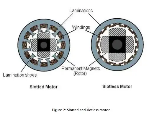
Steel laminations in the stator can be slotted or slotless as shown in Figure 2. A slotless core has lower inductance, thus it can run at very high speeds. Because of the absence of teeth in the lamination stack, requirements for the cogging torque also go down, thus making them an ideal fit for low speeds too (when permanent magnets on the rotor and tooth on the stator align with each other then, because of the interaction between the two, an undesirable cogging torque develops and causes ripples in speed). The main disadvantage of a slotless core is the higher cost because it requires more winding to compensate for the larger air gap.
Proper selection of the laminated steel and windings for the construction of stator is crucial to motor performance. An improper selection may lead to multiple problems during production, resulting in market delays and increased design costs.
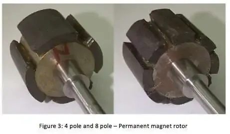
2. Rotor- BLDC motor incorporates a permanent magnet in the rotor. The number of poles in the rotor can vary from 2 to 8 pole pairs with alternate south and north poles depending on the application requirement. In order to achieve maximum torque in the motor, the flux density of the material should be high. A proper magnetic material for the rotor is needed to produce the required magnetic field density.
The rotor of a typical BLDC motor is made out of permanent magnets. Depending upon the application requirements, the number of poles in the rotor may vary. Increasing the number of poles does give better torque but at the cost of reducing the maximum possible speed. Another rotor parameter that impacts the maximum torque is the material used for the construction of a permanent magnet; the higher the flux density of the material, the higher the torque.
Ferrite magnets are inexpensive, however, they have a low flux density for a given volume. Rare earth alloy magnets are commonly used for new designs. Some of these alloys are Samarium Cobalt (SmCo), Neodymium (Nd), and Ferrite and Boron (NdFeB). The rotor can be constructed with different core configurations such as the circular core with a permanent magnet on the periphery, a circular core with rectangular magnets, etc.
3. Hall Sensors- Hall sensor provides the information to synchronize stator armature excitation with rotor position. Since the commutation of the BLDC motor is controlled electronically, the stator windings should be energized in sequence in order to rotate the motor. Before energizing a particular stator winding, acknowledgment of the rotor position is necessary. So the Hall Effect sensor embedded in the stator senses the rotor position.
Most BLDC motors incorporate three Hall sensors which are embedded into the stator. Each sensor generates Low and High signals whenever the rotor poles pass near it. The exact commutation sequence to the stator winding can be determined based on the combination of these three sensors’ responses.
Working Principles and Operation
The underlying principles for the working of a BLDC motor are the same as for a brushed DC motor; i.e., internal shaft position feedback. In the case of a brushed DC motor, feedback is implemented using a mechanical commutator and brushes. With a BLDC motor, it is achieved using multiple feedback sensors. The most commonly used sensors are hall sensors and optical encoders. Note: Hall sensors work on the hall-effect principle that when a current-carrying conductor is exposed to the magnetic field, charge carriers experience a force based on the voltage developed across the two sides of the conductor.
If the direction of the magnetic field is reversed, the voltage developed will reverse as well. For Hall-effect sensors used in BLDC motors, whenever rotor magnetic poles (N or S) pass near the hall sensor, they generate a HIGH or LOW-level signal, which can be used to determine the position of the shaft.
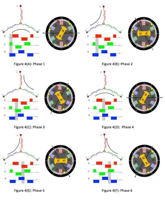
In a commutation system – one that is based on the position of the motor identified using feedback sensors – two of the three electrical windings are energized at a time as shown in figure 4.
In figure 4 (A), the GREEN winding labeled “001” is energized as the NORTH pole, and the BLUE winding labeled “010” is energized as the SOUTH pole. Because of this excitation, the SOUTH pole of the rotor aligns with the GREEN winding and the NORTH pole aligns with the RED winding labeled “100”. In order to move the rotor, the “RED” and “BLUE” windings are energized in the direction shown in figure 4(B). This causes the RED winding to become the NORTH pole and the BLUE winding to become the SOUTH pole. This shifting of the magnetic field in the stator produces torque because of the development of repulsion (Red winding – NORTH-NORTH alignment) and attraction forces (BLUE winding – NORTH-SOUTH alignment), which moves the rotor in the clockwise direction.
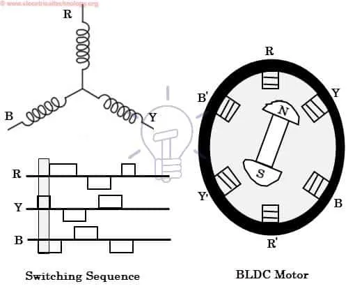
This torque is at its maximum when the rotor starts to move, but it reduces as the two fields align with each other. Thus, to preserve the torque or to build up the rotation, the magnetic field generated by the stator should keep switching. To catch up with the field generated by the stator, the rotor will keep rotating. Since the magnetic field of the stator and rotor both rotate at the same frequency, they come under the category of synchronous motor.
This switching of the stator to build up the rotation is known as commutation. For 3-phase windings, there are 6 steps in the commutation; i.e., 6 unique combinations in which motor windings will be energized.
Brushless Motor Drive
As described above that the electronic controller circuit energizes appropriate motor winding by turning transistors or other solid-state switches to rotate the motor continuously. The figure below shows the simple BLDC motor drive circuit which consists of a MOSFET bridge (also called an inverter bridge), electronic controller, hall effect sensor, and BLDC motor.
Here, Hall-effect sensors are used for position and speed feedback. The electronic controller can be a microcontroller unit or microprocessor or DSP processor or FPGA unit or any other controller. This controller receives these signals, processes them, and sends the control signals to the MOSFET driver circuit.
In addition to the switching for a rated speed of the motor, additional electronic circuitry changes the motor speed based on the required application. These speed control units are generally implemented with PID Controller to have precise control. It is also possible to produce four-quadrant operation from the motor whilst maintaining good efficiency throughout the speed variations using modern drives.
Torque and Efficiency
For the study of electric motors, torque is a very important term. By definition, torque is the tendency of a force to rotate an object about its axis.

Thus, to increase the torque, either force has to be increased – which requires stronger magnets or more current – or distance must be increased – for which bigger magnets will be required. Efficiency is critical for motor design because it determines the amount of power consumed. A higher-efficiency motor will also require less material to generate the required torque.
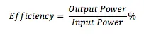
Where,

Having understood the above-provided equations, it becomes important to understand the speed vs. torque curve.
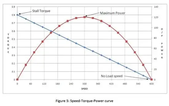
Following are the takeaways from the graph shown in Figure 5:
- With an increase in speed, the torque reduces (considering the input power is constant).
- Maximum power can be delivered when the speed is half of the “no-load” speed and torque is half of the stall torque.