Project-1: Powertrain for aircraft in runways
PART A
1.
The different terms represent different weights or masses. For each flight, the weights are taken into account for several reasons. A brief description of these is below:
Manufacturer's empty weight (MEW)
Also called Manufacturer's Weight Empty (MWE) or Licensed Empty Weight
It is the weight of the aircraft "as-built" and includes the weight of the structure, power plant, furnishings, installations, systems, and other equipment that are considered an integral part of an aircraft.
This excludes any baggage, passengers, or usable fuel.
Zero-fuel weight (ZFW)
This is the total weight of the airplane and all its contents (including unusable fuel), but excluding the total weight of the usable fuel on board.
As a flight progresses and fuel is consumed, the total weight of the airplane reduces, but the ZFW remains constant.
Maximum zero fuel weight (MZFW) is the maximum weight allowed before usable fuel and other specified usable agents (engine injection fluid, and other consumable propulsion agents) are loaded.
Operating empty weight (OEW) (Roughly equivalent to basic empty weight on light aircraft)
It is the aircraft's basic weight, including the crew, all fluids necessary for operation such as engine oil, engine coolant, water, unusable fuel, and all operator items and equipment required for flight but excluding usable fuel and the payload.
Payload
It is the carrying capacity of an aircraft. It includes cargo, people, and extra fuel. In the case of a commercial airliner, it may refer only to revenue-generating cargo or paying passengers.
Maximum takeoff weight (MTOW)
This is the maximum weight at which the aircraft pilot is allowed to attempt to take off.
Regulated takeoff weight (RTOW)
Depending on different factors (e.g. flap setting, altitude, air temperature, length of runway), RTOW or maximum permissible takeoff weight varies for each takeoff. It can never be higher than MTOW.
Maximum landing weight (MLW)
This maximum weight at which an aircraft is permitted to land.
The following image depicts takeoff weight components.
Maximum ramp weight (MRW)
also called maximum taxi weight (MTW)
It is the maximum weight authorized for maneuvering (taxiing or towing) an aircraft on the ground.
Aircraft gross weight
It is the total aircraft weight at any moment during the flight or ground operation. This decreases during the flight due to fuel and oil consumption.
TYPES OF AIRCRAFT
There are several ways to identify aircraft by type. The primary distinction is between those that are lighter than air and those that are heavier than air.
Aircraft such as balloons, nonrigid airships (blimps), and dirigibles are designed to contain within their structure a sufficient volume that, when filled with a gas lighter than air (heated air, hydrogen, or helium), displaces the surrounding ambient air and floats, just as a cork does on the water. Balloons are not steerable and drift with the wind. Nonrigid airships, which have enjoyed a rebirth of use and interest, do not have a rigid structure but have a defined aerodynamic shape, which contains cells filled with the lifting agent. They have a source of propulsion and can be controlled in all three axes of flight. Dirigibles are no longer in use, but they were lighter-than-air craft with a rigid internal structure, which was usually very large, and they were capable of relatively high speeds. It proved impossible to construct dirigibles of sufficient strength to withstand routine operation under all weather conditions, and most suffered disaster, either breaking up in a storm, as with the U.S. craft Shenandoah, Akron, and Macon or through ignition of the hydrogen, as with the German Hindenburg in 1937.
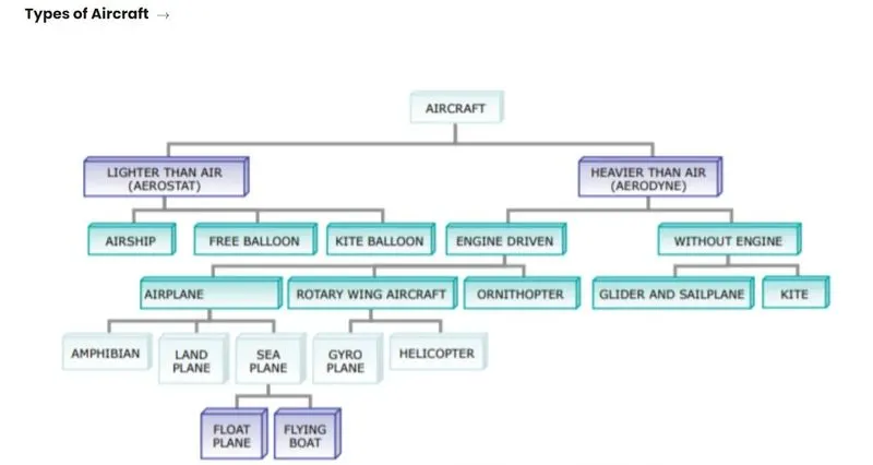
types of airplanes and their weights
1. airbus 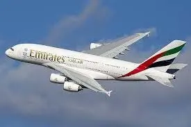
weight : 500-600 tons
2. Piston Aircraft 3. JETS: they weigh between 10.15 to 22.5 tons
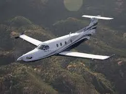
4. Turboprop: 5 tons
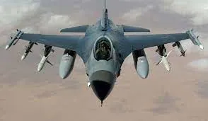
4. Turboprop: 5 tons 5. Narrow-body aircraft
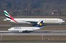
6. Wide body airliners 7. Commuter liners: 55 to 57 tons
120 - 199 tons
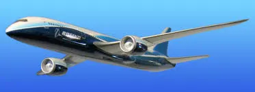
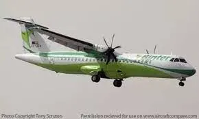
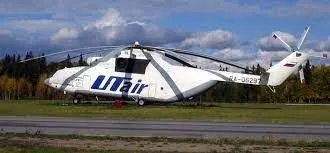
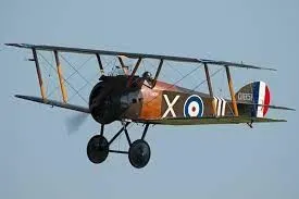
8. helicopter: 0.4 to 61 tons 9. Biplanes
2.
GROUND SPEED:
Ground speed is the horizontal speed of an aircraft relative to the Earth’s surface. It is vital for accurate navigation that the pilot has an estimate of the ground speed that will be achieved during each leg of a flight.
An aircraft diving vertically would have a ground speed of zero. The information displayed to passengers through the entertainment system of airline aircraft usually gives the aircraft ground speed rather than airspeed.
Ground speed can be determined by the vector sum of the aircraft's true airspeed and the current wind speed and direction; a headwind subtracts from the ground speed, while a tailwind adds to it. Winds at other angles to the heading will have components of either headwind or tailwind as well as a crosswind component.
AIRSPEED:
An airspeed indicator is a differential pressure gauge with the pressure reading expressed in units of speed, rather than pressure. The airspeed is derived from the difference between the ram air pressure from the pitot tube, or stagnation pressure, and the static pressure. The pitot tube is mounted facing forward; the static pressure is frequently detected at static ports on one or both sides of the aircraft. Sometimes both pressure sources are combined in a single probe, a pitot-static tube. The static pressure measurement is subject to error due to the inability to place the static ports at positions where the pressure is true static pressure at all airspeeds and attitudes. The correction for this error is the position error correction (PEC) and varies for different aircraft and airspeeds. Further errors of 10% or more are common if the airplane is flown in an “uncoordinated” flight.
DIFFERENCE BETWEEN AIRSPEED AND GROUND SPEED:
- While ground speed is the airplane’s speed relative to the surface of the Earth, airspeed – at least true airspeed is its speed relative to the air it is flying in.
-
true airspeed is simply the speed at which an aircraft is moving relative to the air it is flying in. As such, it’s also the speed at which the air is flowing around the aircraft’s wings. Ground speed, on the other hand, is the aircraft’s speed relative to the ground. One thing that should be noted here is that it’s horizontal rather than vertical speed – an aircraft climbing completely vertically would have a ground speed of zero.
- Ground speed is simply the sum of airspeed and wind speed.
- If the aircraft is flying in the same direction as the wind is blowing, the aircraft experiences tailwind, and its ground speed is higher than its airspeed. On the other hand, if the wind is blowing against the direction the aircraft is traveling in, the aircraft experiences a headwind, and its ground speed is lower than its airspeed.
-
For pilots, both airspeed and ground speed is very important. While the first one helps them make sure they are flying fast enough to take off, not stall, and so on, the second one helps them figure out how long it will take them to get from one place to another.
On the other hand, if you are a passenger, you will only need to be concerned about the ground speed as that will tell you how fast are you flying from your origin to your destination – how fast you will be able to get to your meeting, meet your relatives, or do whatever else the reason for your travel might be.
3.
- Although many aircraft are capable of moving in backward using reverse thrust, as a result, the jet blast or prop wash might cause damage to the terminal building or equipment. Engine close to the ground may also blow sand and debris forward and then suck them into the engine, causing damage to the engine.
- Engines can blow sand and debris.
- Engines can suck in sand and debris which can cause serious damage to the engine.
- The push-back truck driver knows the airport better than the pilot.
- It is easier for the truck driver to see the surroundings better than the pilot sitting in the cockpit with limited windows.
- The plane engines are very loud. This noise can add up substantially when multiple planes are moving around the airport. It won't be a pleasant experience for the people sitting inside the terminal as most people don't even like the sound of powerful motorbikes.
- It is also not recommended to use aircraft engine power to move it on the ground at the airport as it also saves fuel.
- The modern planes are huge. It is difficult to navigate such gigantic structures through limited space. An A380 is 8 stories high. The pilots won't be able to see anything in front of them or anything behind the wings.
- Push back is for moving the aircraft backward from the gate, and throwing or taxing is the procedure to move the aircraft. These machineries are called aircraft tugs. Aircraft tunes are real modern Marvels, moving aircraft weight 100 tons all day, every day. A true pushback tug aims to allow the operator to have excellent visibility of the attaching mechanism between the airplane and tug.
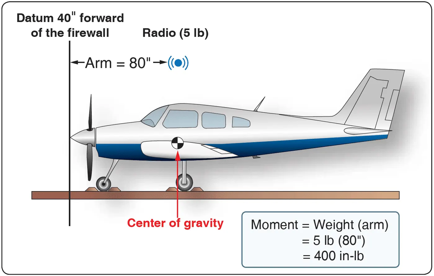
- While moving the aircraft in the reverse direction by applying the forward thrust care must be taken because the reverse thrust is unsafe when stopped or at low speed. This is because the nose may lift, dropping the tail onto the tarmac. The cause is the engines being at some considerable height from the ground and the aircraft's center of gravity being just ahead of the main wheelset. Additionally, once moving backward, if the aircraft's breaks are used the same can happen, that is the plane can sit on its tail.
4.
Airplanes have engines, and they can use them to move forward along the ground. So they push themselves to the runway. Most of the time, a small vehicle is indeed needed to push the larger commercial airplanes backward away from the terminal building because even if a plane can reverse its thrust, it’s not always safe to hit the buildings with that reverse thrust. So the little trucks push the bigger planes back away from the buildings, but after that, the planes can apply a small amount of engine power to roll forward just as all airplanes can. Aircraft push themselves to the runway.
Towing:
In the parking areas were taxing the aircraft is not practical or is unsafe such as moving aircraft in and out of maintenance hangars, or moving aircraft that are not under their power or moving backward, then towing of aircraft is performed using the power of a specialized ground vehicle attached to or supporting the nose landing gear. The traditional method of allowing the ground vehicle to move an aircraft is to attach it to the aircraft's nose landing gear by the means of a towbar.
As the pilot can't see what is behind the aircraft steering is done by push back truck driver and depending on the aircraft type and airline procedure a bypass pin may be temporarily installed into the nose gear to disconnect from the aircraft's normal steering mechanism. Once the towing is completed the tow bar is disconnected and the aircraft can tax forward under its power.
Taxing:
Taxing is the movement of an aircraft on the ground under its power while on the surface. The aircraft always moves following the yellow lines to avoid collision with the surrounding buildings, vehicles, or other aircraft. The taxing motion has a speed limit. Before making a turn the pilot reduces speed to prevent tire skids just like other vehicles. The reason for taxing is to reach the vehicle into the runway or from runway to terminal.
Takeoff:
After taxing when the aircraft reaches the runway the take-off takes place. Takeoff is the phase of flight in which an aircraft goes through the transition from moving along the ground to flying in the air. Usually, the engines run at full power during takeoff. Following the taxi motion, the aircraft stops at the starting line of the runway. Before take-off, the engines, particularly piston engines, are routinely run up at high power to check for engine-related problems. This makes considerable noise. When the pilot release is the breaks the aircraft starts accelerating rapidly until the necessary speed for takeoff is achieved. The take of speed required varies with air density aircraft weight and aircraft configuration. Air density is affected by factors such as field elevation and air temperature.
5.
Take off the power:
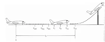
The amount of power that an engine is allowed to produce for a limited period for takeoff. The use of takeoff power is usually limited to 5 min for reciprocating engines and up to 2½ min for gas turbine engines. This may not always be the case. Specifically, concerning reciprocating engines, it is the brake horsepower developed under standard, sea-level conditions and the maximum conditions of the crankshaft rotational speed and the engine manifold pressure approved for the normal takeoff. It is limited in continuous use to the period shown in the approved engine specifications. Concerning gas turbine engines, it is the thrust developed under static conditions at a specified altitude and atmospheric conditions of the rotor shaft rotational speed and gas temperature approved for the normal takeoff. It is limited in continuous use to the period shown in the approved engine specifications.
Tire design:
When it comes to safety, tires are one of the most important components of aircraft. They help to absorb the shock of landing and provide cushioning. It also provides the necessary traction for braking and stopping an aircraft. An aircraft tire is designed to withstand extremely heavy loads while landing, taking off, taxing, and parking. The number of wheels required for aircraft increases with the weight of the aircraft, as the weight of the airplane needs to be distributed more evenly. A Boeing 737NG & 737MAX uses 6 wheels, Boeing 787 uses 10 wheels, Boeing 777 uses 14 wheels and Airbus A380 uses 22 wheels. Aircraft tires work under extreme conditions, carrying up to 340 tons and accelerating at over 250 km/hour at takeoff, in addition to enduring varied environmental stress when in flight and taxiing.
Carcass plies are used to form the tire. They are sometimes called casing plies. An aircraft tire is constructed for the purpose it serves.
- They support the weight of an aircraft while it is on the ground.
- It also provides the necessary traction for braking and stopping an airplane.
- Tyre also helps to absorb the shock of landing and provides cushioning for the roughness of takeoff, roll-out, and taxi operations.
Unlike an automobile or truck tire, it does not have to carry a load for a long period of continuous operation. However, an aircraft tire absorbs the high impact loads of landing, and also it’s operating at high speeds for a short time when required.
Retreading – Retreading is a method of restoring a worn tire by renewing the tread area or by renewing the tread area plus one or both sidewalls. Repairs are included in the tire retreading process.
Load Rating – Load rating is the maximum permissible load at a specified inflation pressure.
Ply Rating – Ply Rating is used to identify the maximum recommended load rating and inflation pressure for a specified tire. It is an index of tire strength.
Speed Rating – The speed rating is the maximum takeoff speed to which the tire has been tested.
Skid Depth – Skid depth is the distance between the tread surface and the deepest groove as measured in the mold.
Aircraft tires must have an approved speed and load rating and have sufficient clearance when retracted through landing gear to allow for tire growth. Tire growth is the increase in the size of the tire due to centrifugal forces at high speed. Tubeless tires are more advantageous over tube-type. There is no longer the use of tube-type tires in recent aviation. Nowadays all airliners are using tubeless tires. Tubeless that are meant to be used without a tube have the word TUBELESS on the sidewall of the tire. Almost all airliners are using Radial tires. Bias is an older design, and it’s mainly used for road vehicles. Radial tires have the word RADIAL on the sidewall. Radial tires are more expensive than bias-ply tires. Radial tires are in demand because of their lower life cycle cost and long-term value. Today’s tires are conductive. Aircraft tires are manufactured with tread rubber with conducting compounds to permit earthing of static charges.
Rolling resistance:
Tire rolling resistance is the energy that your vehicle needs to send to your tires to maintain movement at a consistent speed over a surface. In other words, it is the effort required to keep a tire rolling. The main contributor to rolling resistance is the process known as hysteresis.
Rolling Resistance Coefficient μR is defined by μR = F/G, where F is the force necessary to pull the axle of a tire horizontally in the direction of travel, and G is the vertical load on the tire which is assumed to roll on a flat horizontal surface.
The coefficient of rolling resistance for a pneumatic tire used in motor vehicles on smooth asphalt or concrete surface is indicated in the range of 0.007 to 0.02 [1-9], most often indicated around 0.012.
Tire pressure:
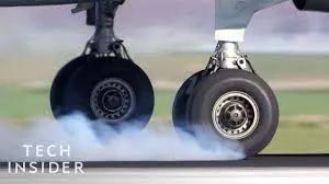
An aircraft tire or tire is designed to withstand extremely heavy loads for short durations. The number of tires required for aircraft increases with the weight of the aircraft, as the weight of the airplane needs to be distributed more evenly. Aircraft tire tread patterns are designed to facilitate stability in high crosswind conditions, to channel water away to prevent hydroplaning, and for braking effect. Aircraft tires also include fusible plugs (which are assembled on the inside of the wheels), designed to melt at a certain temperature. Tires often overheat if maximum braking is applied during an aborted takeoff or an emergency landing. The fuses provide a safer failure mode that prevents tire explosions by deflating in a controlled manner, thus minimizing damage to aircraft and objects in the surrounding environment.
Aircraft tires generally operate at high pressures, up to 200 psi (14 bar; 1,400 kPa) for airliners, and even higher for business jets. The main landing gear on the Concorde was typically inflated to 232 psi (16.0 bar), whilst its tail bumper gear tires were as high as 294 psi (20.3 bar). The high pressure and weight load on the Concorde tires were a significant factor in the loss of Air France Flight 4590.
Brake forces while landing:
Airplanes rely on a braking system to safely land on runways. At cruising altitude, most commercial airplanes fly at a speed of roughly 500 to 600 mph. When landing, however, they must reduce their speed. A typical 747, for instance, has a landing speed of about 160 to 170 mph. And upon touching the runway, airplanes must quickly brake until they come to a complete stop.
WING SPOILERS:
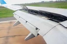
Many airplanes use wing spoilers to assist with braking when landing. Not to be confused with ailerons, spoilers are extendable flaps on the ends of an airplane’s wings. Pilots can raise the spoilers to decelerate the airplane as it approaches the runway. And even while on the runway, pilots will typically leave the wing spoilers raised. Raised wing spoilers create the drag, which essentially slows down the airplane so that it’s able to brake more quickly.
DISC BRAKES:
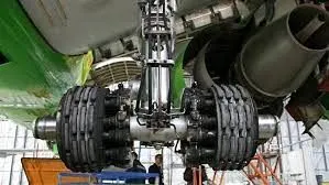
In addition to wing spoilers, airplanes use disc brakes. Airplane disc brakes are similar to the braking system in automobiles. They consist of a pair of calipers that, when engaged, squeeze pads against the rotors of an airplane’s landing gear.
Disc brakes are designed to remain static at all times. In other words, they don’t rotate with the wheels of an airplane’s landing gear. As the wheels turn, the disc brakes will remain static and stationary. They are a vital component of an airplane’s braking system because they are designed to apply pressure to the airplane’s wheels. Disc brakes will squeeze the wheels, thereby slowing down the speed at which they spin. In turn, this reduces the speed of the airplane so that it can come to a complete stop on the runway.
REVERSE THRUST:
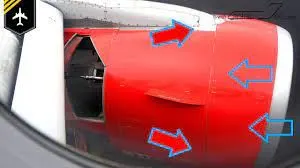
Finally, many jet airplanes use reverse thrust to assist with braking during landings. Reverse thrust is a feature in jet engine airplanes that, as the name suggests, involves the reversal of the engines’ thrust. When flying, the thrust is projected out the rear of an airplane’s engines. When landing, however, pilots may use the reverse thrust feature. Reverse thrust changes the direction of the engine’s thrust. Rather than projecting out the rear, the thrust will be projected out the front. This reversal of thrust provides deceleration that allows airplanes to slow down more quickly when landing.
PART B
6.
A.
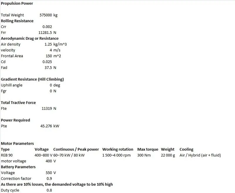
TRACTION FORCE: Traction force is the force used to generate motion between a body and a tangential surface through the use of dry friction, though shear force is also commonly used. Traction can also refer to the maximum tractive force between a body and a surface, as limited by available friction; when this is the case, traction is often expressed as the ratio of the maximum tractive force to the normal force and is termed the coefficient of traction.
To push or pull an aircraft, 3 types of forces act on the vehicle.
- rolling resistance
- aerodynamic drag
- hill-climbing force.
a. Rolling resistance: This is the force resisting the motion when a body rolls on the surface. It is the frictional force that is needed to overcome to move a vehicle. In other words, it is the effort required to keep a tire rolling. The main contributor to rolling resistance is the process known as hysteresis.
Rolling Resistance Coefficient μR is defined by μR = F/G, where F is the force necessary to pull the axle of a tire horizontally in the direction of travel, and G is the vertical load on the tire which is assumed to roll on a flat horizontal surface.
b. Aerodynamic force: An aerodynamic force is a force exerted on a body by the air (or other gas) in which the body is immersed, and is due to the relative motion between the body and the gas.
It is defined as,
Fad = 0.5*ρ*A*Cd*V^2
Where,
ρ = air density
A = frontal area
Cd = drag coefficient
V = velocity.
c. Hill climbing force:
The force required for a vehicle to climb on a slope of ab angle is called the hill-climbing force.
Fhc = mgsinψ
where, m = mass of vehicle
g = gravity = 9.8
ψ = angle of slope
total force required
Fte = Frr + Fad + Fhc + Fla + Fwa
B. MATLAB SIMULATION
%assumed values
Urr = [0.02,0.03,0.04,0.05,0.06,0.07]; %rolling resistance coefficient ARRAY
u = 0.8;
m = linspace(50000,60000,10); %mass in kg ARRAY
g = 9.81; %acceleration of gravity in m/sec^2
rho = 1.25; %air density in kg.m^3
A = 158.3; %frontal area in m^2
Cd = 0.02; %drag coefficient
v = 3; %velocity in m/s
r = 0.35; %wheel radius of towing vehicle in m
G = 20; %gear ratio
Frr = zeros(6,10); %array to store rolling resistance force
Fad = zeros(6,10); %array to store aerodynamic force
Ffr = zeros(6,10); %array to store frictional force
Fte = zeros(6,10); %array to store total traction force
%for loop for force calculation
for i = 1:6
for j = 1:10
Frr1 = Urr(i).*m(j)*g;
Frr(i,j) = Frr1;
Fad1 = 0.5*rho*A*Cd*v^2;
Fad(i,j) = Fad1;
Ffr1 = u*m(j).*g;
Ffr(i,j) = Ffr1;
Fte(i,j) = Frr(i,j) + Fad(i,j) + Ffr(i,j); %total traction force
end
end
>> display(Fte)
Fte =
1.0e+05 *
4.0223 4.1117 4.2010 4.2904 4.3798 4.4692 4.5586 4.6479 4.7373 4.8267
4.0713 4.1618 4.2523 4.3427 4.4332 4.5237 4.6141 4.7046 4.7951 4.8856
4.1204 4.2119 4.3035 4.3951 4.4866 4.5782 4.6697 4.7613 4.8529 4.9444
4.1694 4.2621 4.3547 4.4474 4.5400 4.6327 4.7253 4.8180 4.9106 5.0033
4.2185 4.3122 4.4060 4.4997 4.5934 4.6872 4.7809 4.8747 4.9684 5.0621
4.2675 4.3624 4.4572 4.5520 4.6468 4.7417 4.8365 4.9313 5.0262 5.1210
>> %power calculation
>> P = (Fte*v)/1000; %aiecraft power calculation in kW
>>
>> %Torque calculation
>> T = (Fte*r)/G;
>>
>> plotting
Unrecognized function or variable 'plotting'.
>> %PLOTTING
>> figure
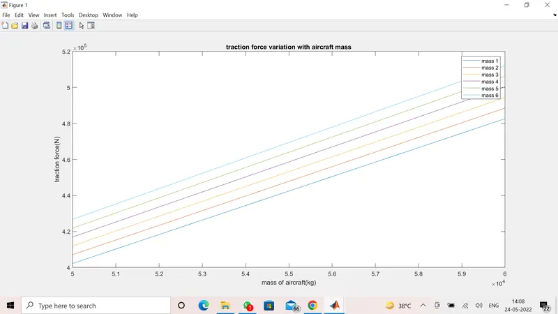
>> plot(m,Fte)
>> Xlabel('mass of aircraft(kg)') %X axis
Unrecognized function or variable 'Xlabel'.
Did you mean:
>> xlabel('mass of aircraft(kg)') %X axis
>> ylabel('traction force(N)') %y axis
>> title('traction force variation with aircraft mass')
>> legend("Icy concreat/asphalt - 0.02", "Dry concreat/asphalt - 0.03", "Firm turf - 0.04", "Hard turf - 0.05", "Wet concreat/asphalt - 0.06", "Soft turf - 0.07")%legend
>>
>> figure
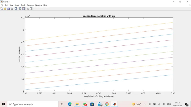
>> plot(Urr,Fte)
>> xlabel('coefficient of rolling resistance')
>> ylabel('traction force(N)')
>> title('traction force variation with Urr')
>> legend("mass 1", "mass 2", "mass 3", "mass 4", "mass 5", "mass 6", "mass 7", "mass 8", "mass 9", "mass 10") % legend
RESULT:
7.
| Assumed Parameters | ||
| Mass of aircraft | 575000 | kg |
| Mass of the push back truck | 1000 | kg |
| Coefficient of Rolling Resistance | 0.002 | |
| Drag Coefficient | 0.025 | |
| Air density | 1.125 | kg/m^3 |
| Frontal Area | 150 | m^2 |
| Velocity | 4 | m/s |
| Uphill gradient | 0 | deg |
| Battery Voltage | 550 | V |
| Correction Factor | 0.8 | |
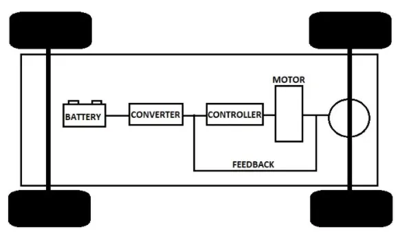
Block Diagram:
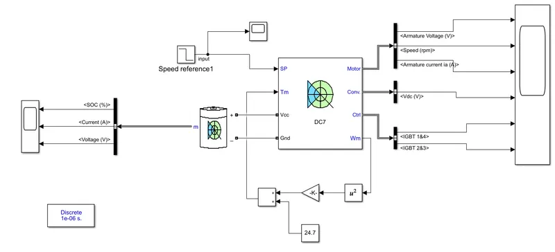
Simulink Model:
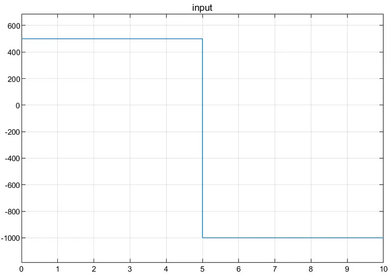
Input:
Output:
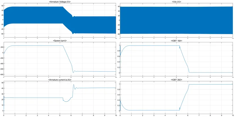
From the motor:
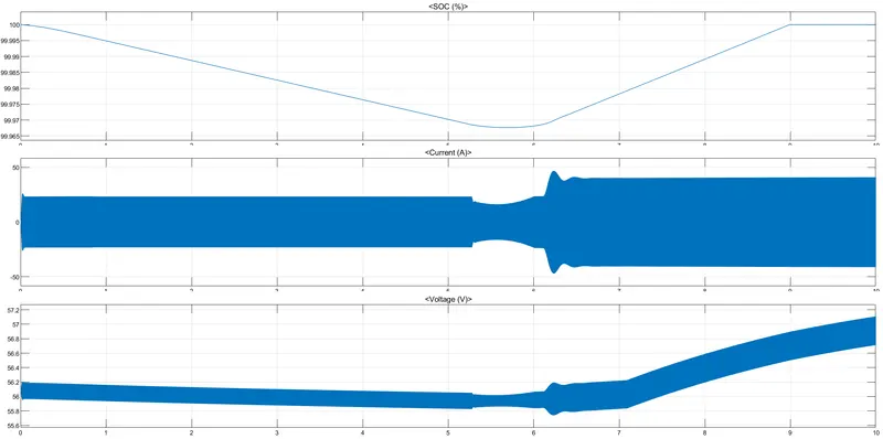
From the Battery:
B. Also, Design the parameters in an excel sheet.