Week-7 Challenge: DC Motor Control
- A. Explain a MATLAB demo model named ‘Speed control of a DC motor using BJT H-bridge’.
1.A
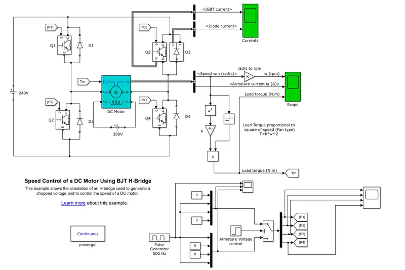
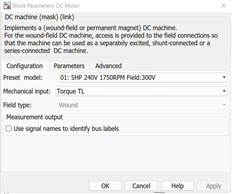
Here the DC motor used is 5HP, 240 V, 1750 rpm with a field voltage of 300 V.
Hence the field terminals are connected with a field voltage of 300 V and armature terminals are connected to 240 V battery through IGBTs. Feedback diodes are kept in parallel to handle the reverse power flow.
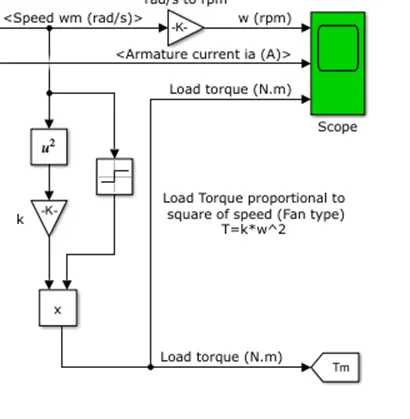
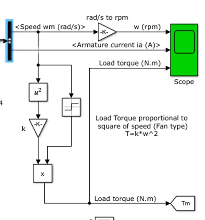
The DC motor is feeding a fan type of load (T = K*W^2).
Circuit for providing gate pulses to IGBT is as shown below:
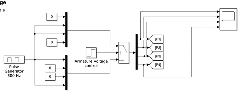
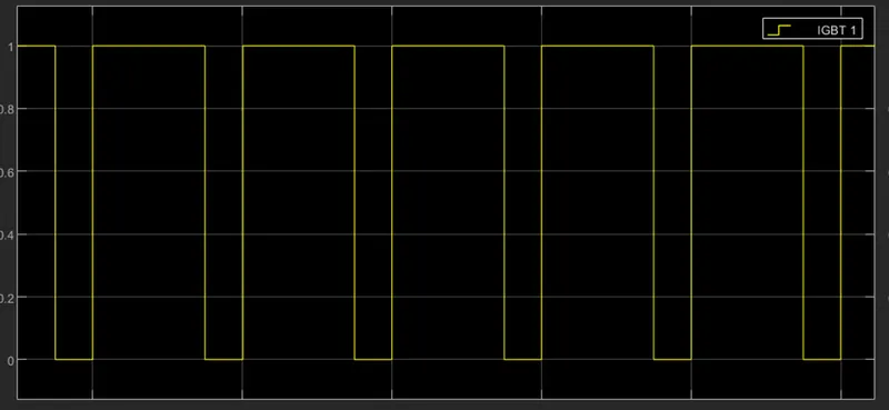
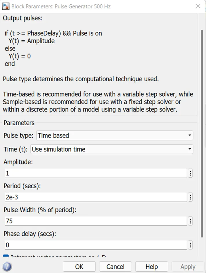
The frequency of gate signal is 500 Hz. So, time period = (1/500) = 2e^-3 secs.
We have chosen a duty cycle of 75 %. The gate pulses to each IGBT looks like:
The block parameters of pulse generator for 500 Hz frequency and 75% duty cycle is given as below:
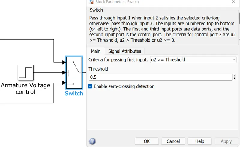
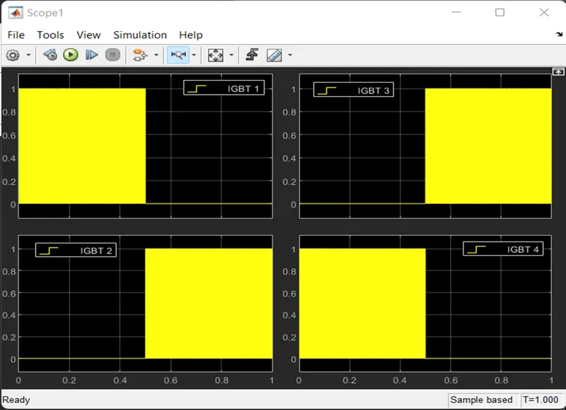
The gate signal for the 4 IGBTs are generated by using a switch logic where IGBTs 1 and 4 conduct for half of the time period and IGBTs 2 and 3 for the remaining half. The logic is implemented with the help of a step input setting the criteria for passing the input to the switch.
At each instant, firing of devices on the same leg is avoided (by generating complimentary gate signals) to avoid short circuit conditions, as is very evident from 4 gate pulses as shown below:
In the model we are using a bus selector block to select the parameters to be plotted from motor to scope.
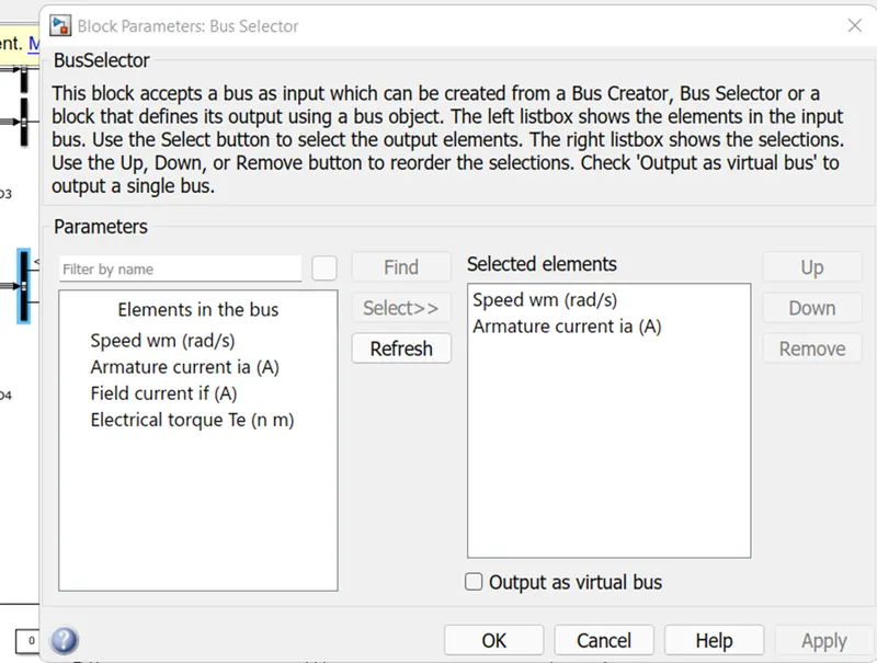
The speed is converted from rad/s to rpm by multiplying with a factor 30/pi. Speed, armature current and load torque are connected to scope.
When IGBTs 1 and 4 are turned ON:
- Positive voltage is applied across the armature terminals of the dc motor.
- Motor is operating in ‘forward motoring mode’.
- Here power is positive, speed is positive and Torque is positive.
When IGBTs 2 and 3 are turned ON:
- Negative voltage is applied across the armature terminals of the dc motor.
- Motor is operating in ‘reverse motoring mode’.
- Here power is still positive, speed is negative and Torque is negative.
The above waveforms are shown below (for half of time period: motoring operation and for remaining half: braking operation)
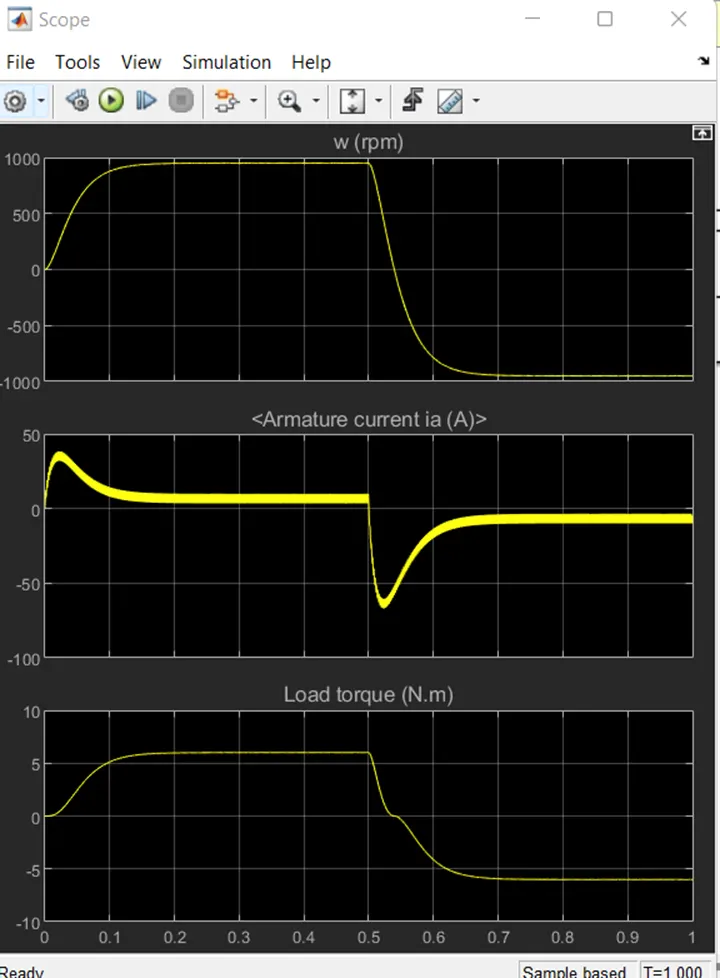
Forward braking mode is the region in the above plot where positive speed reaches zero speed (starting from 0.5 seconds to the time where speed is zero)
Reverse braking mode is not shown in plot and it is the region from the time brakes are applied and speed falls from the negative speed to zero speed.
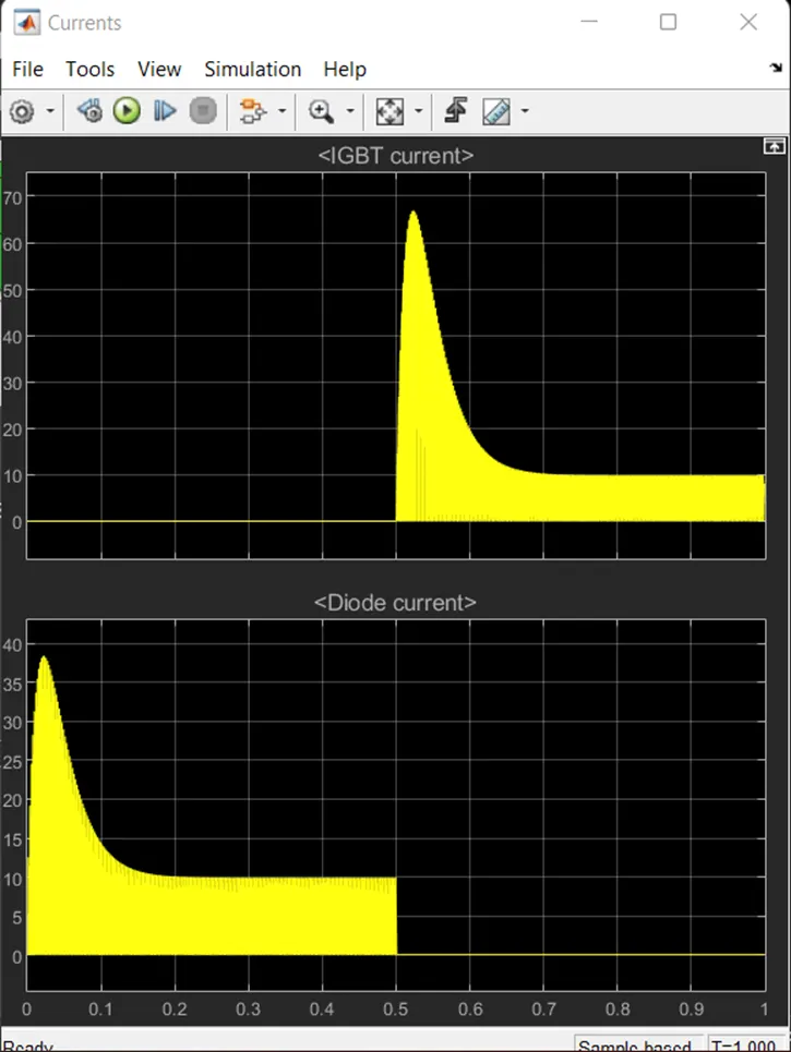
The IGBT current and diode current are also plotted to scope as shown below:

The corresponding waveforms are as shown below:
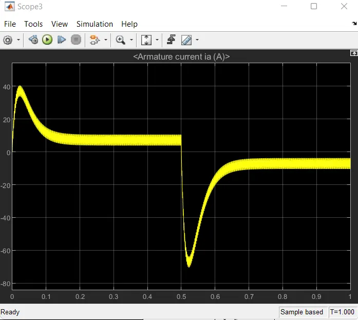
1B. Comment on the armature current shoot-up from the scope results.
Armature current variation is as shown below:
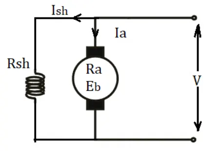
Armature current in a dc motor, Ia = (V - Eb)/Ra ..................(1)
where V ---> DC source voltage
Eb ---->Back emf
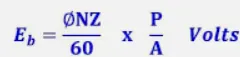
At starting, speed N =0 -----> Back emf Eb = 0
As such, there is no back emf to oppose the applied voltage and the entire voltage is applied across the armature.
Since armature resistance is small, the starting current rises to a high value. In order to avoid this, starters are used at the time of starting (where resistance are connected in series with the armature to reduce the current).
Inorder to reduce starting current, we can also control the applied dc voltage with the help of a chopper. The duty cycle of the chopper can be so controlled that, voltage is applied only gradually. i.e., voltage is incremented in steps ( at starting --> small voltage---> hence small speed and back emf. As the voltage is gradually increased ---> speed and back emf also increases gradually ---> so the starting current is limited from being a large value)
1C Refer to the help section of ‘The Four-Quadrant Chopper DC Drive (DC7) block’. Compare it with the H-bridge model
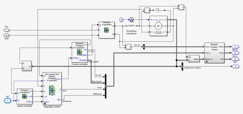
The four quadrant chopper DC drive is shown below:
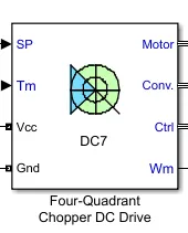
The detailed model is as shown below:
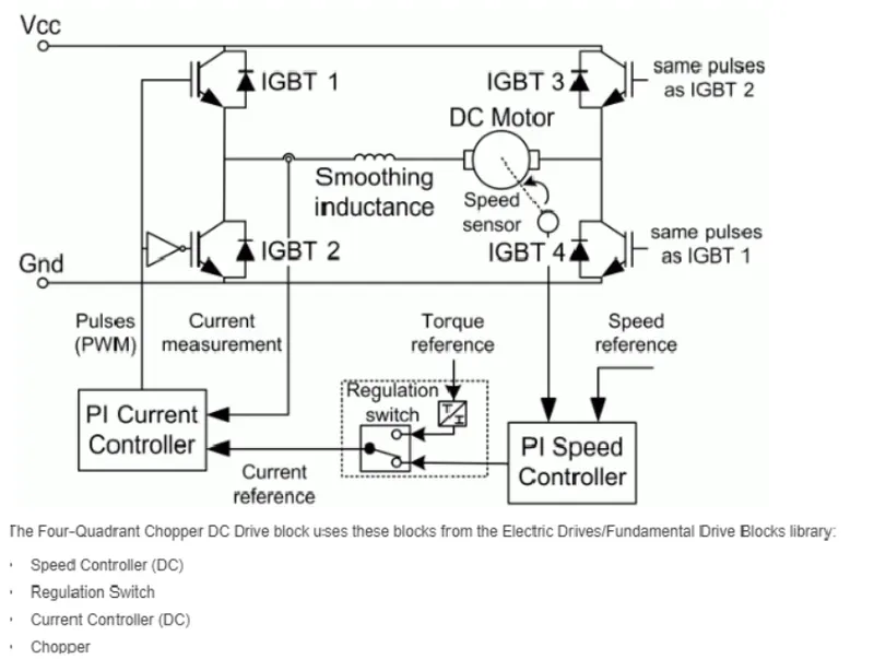
The above model can be represented in a simplified block diagram form as below:
Comparison of four quadrant DC 7 drive block and H bridge model:
|
4-Quadrant DC 7 drive block |
H bridge model |
|
Works in all 4 modes of operation: · Forward motoring · Forward braking · Reverse motoring · Reverse braking |
Works in only 2 modes of operation: · Forward motoring · Reverse motoring |
|
Gate pulses to the switches are generated from a PI current controller whose current reference is set by a PI speed controller which tracks the speed reference |
Gate pulses to the switches are generated from pulse generator |
|
Consists of an outer speed control loop and an inner current control loop |
No speed control and current control loops |
|
Smoothing inductance is used to reduce the di/dt for the smooth control of speed torque characteristics |
No smoothing inductance is used |
|
Closed loop model |
Open loop model |
2. Develop a 2-quadrant chopper using simulink & explain the working of the same with the relevant results.
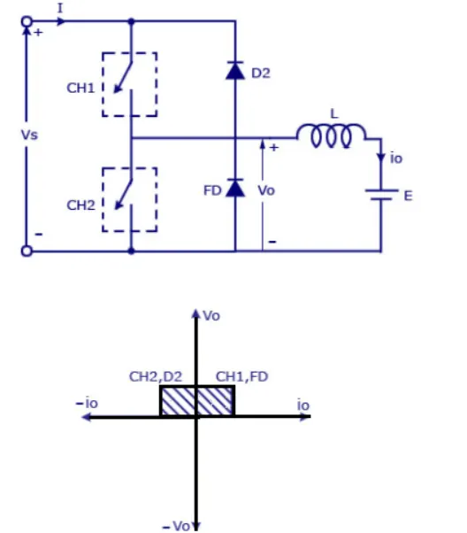
- When CH1 and FD are conducting, V and I are positive, the power is positive and the machine is operating in forward motoring mode. The power flows from source to load (quadrant 1 operation).
- When CH2 and D2 are conducting, V is still positive and current is negative, the power is negative and the machine is operating in forward braking mode. The power flows from load to source (quadrant 2 operation).
The simulink model of a two quadrant chopper is shown below:
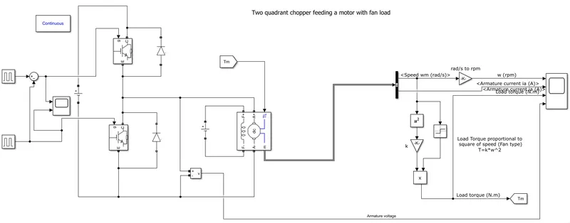
Here the motor is driving a fan type of load. The specifications of motor: 5HP, 240 V, 1750 rpm, field voltage - 300 V.
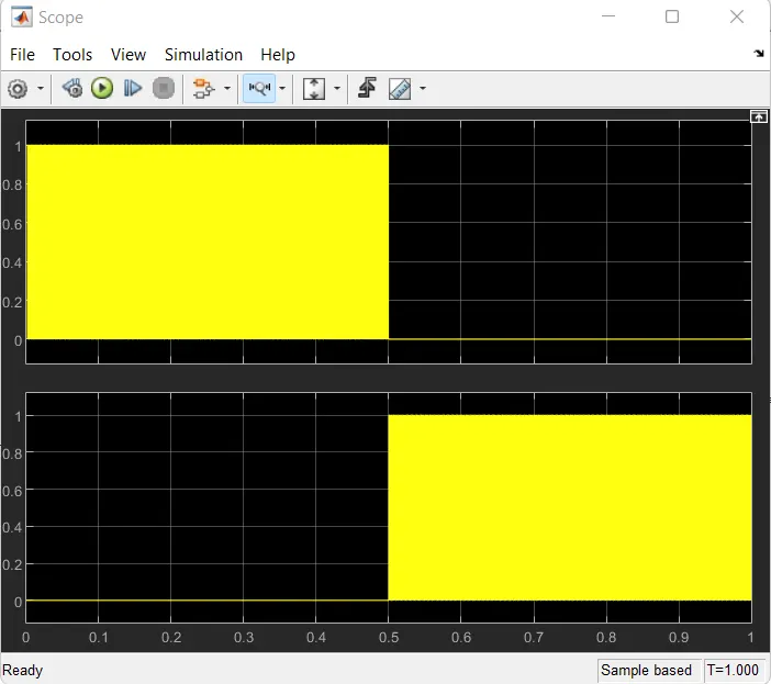
Top switch is turned ON for first half of time period and bottom switch for the remaining half.
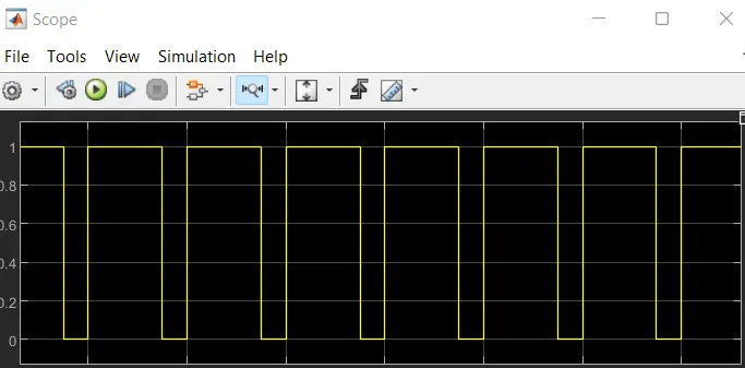
The duty cycle of switches are assumed to be 75% and switching frequency is assumed as 500 Hz.
Gate signals for switches:
Zoomed image of duty cycle:
Scope output is as shown below:
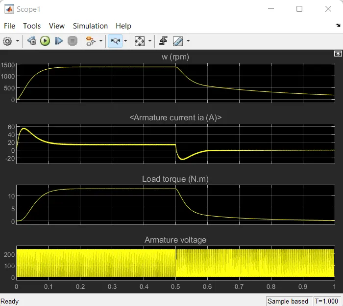
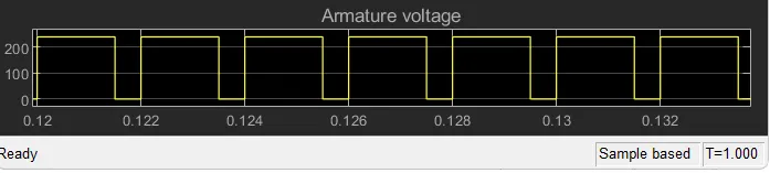
As evident from the plots, armature voltage is always positive but armature current is reversing after half cycle. Thus, upto half time period, the chopper is operating in first quadrant and then the chopper is operating in second quadrant.
3. Explain in brief about operation of BLDC motor.
BLDC motor is an electronically commutated motor where electronic switching circuit replaces the mechanical commutators. The motor works on the principle of Lorentz force. The motor windings are switched electronically by transistors or other solid state switching devices at the correct rotor position in such a way that armature field is in space quadrature with rotor field poles. Hence the force causes the rotor to rotate.
A simple BLDC motor drive circuit which consists of MOSFET bridge (also called as inverter bridge), electronic controller, hall effect sensor and BLDC motor is shown below.
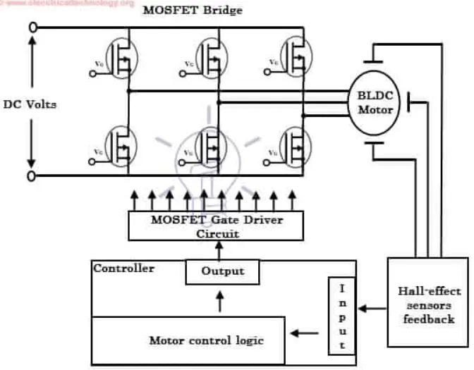
Hall-effect sensors provide position and speed feedback. Microcontroller unit or microprocessor or DSP processor or FPGA unit etc can be used for the electronic control. This controller receives the feedback signals from the sensors, processes them and sends the control signals to the MOSFET driver circuit.
The motor speed can be changed by the implementation of additional electronic circuitry on required application. PID controllers provide precise speed control. Four quadrant operation with proper maintenance of efficiency throughout the speed variation is possible by implementation of modern drives.