Project 2 - Speed Control of a Direct Current (DC) motor
>> edit dcmotor_parameters
dcmotor_parameters.m
%This file contains the design parameters to model a DC Motor
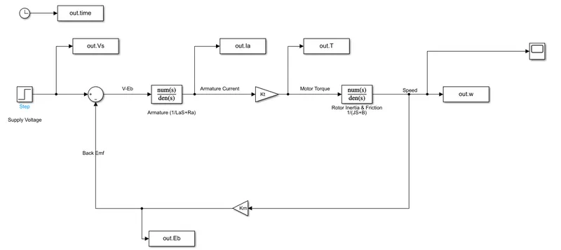
Jm=0.01; % Moment of inertia of rotor in kg-m2
Bm=0.1; % Motor viscous friction constant in N-m-s
Km=0.01; % Back emf constant in V/rad/s
Kt=0.01; % Motor torque constant in N-m/Amp
Ra=1; % Resistance of the armature circuit in ohms
La=0.5; % Inductance of the armature circuit in henries
>> dcmotor_parameters
Simulink Model of a dc motor with the above parameters
>> edit project_plot
project_plot.m
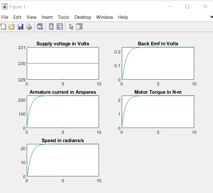
subplot(321);plot(out.time,out.Vs);grid;title('Supply voltage in Volts');
subplot(322);plot(out.time,out.Eb);grid;title('Back Emf in Volts');
subplot(323);plot(out.time,out.Ia);grid;title('Armature current in Amperes');
subplot(324);plot(out.time,out.T);grid;title('Motor Torque in N-m');
subplot(325);plot(out.time,out.w);grid;title('Speed in radians/s');
>> project_plot
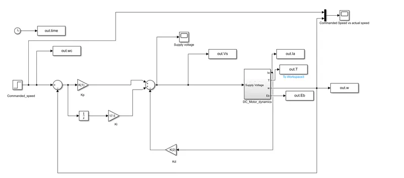
Now we have to control the speed of the above motor by PID control.
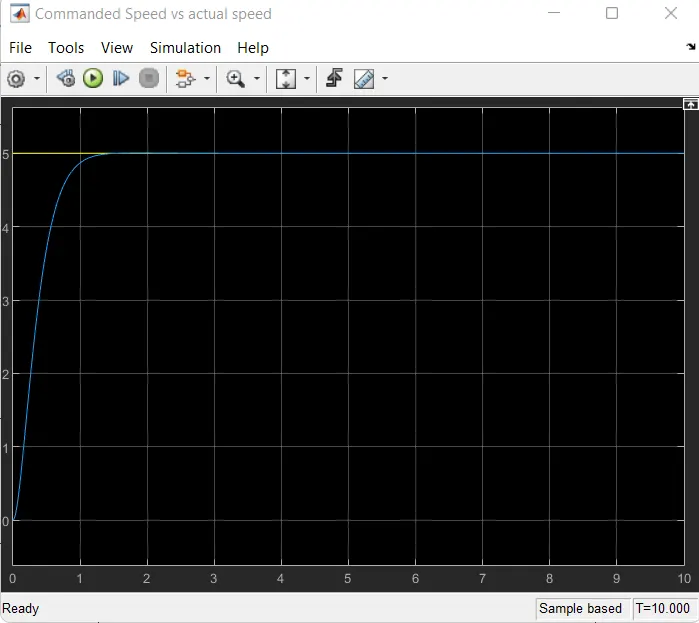
For the model to be simulated, commanded speed is taken as 5 radians/sec and is implemented via a step function. The script dcmotor_parameters is updated as below for the PID control:
>> edit dcmotor_parameters
dcmotor_parameters.m
%This file contains the design parameters to model a DC Motor
Jm=0.01; % Moment of inertia of rotor in kg-m2
Bm=0.1; % Motor viscous friction constant in N-m-s
Km=0.01; % Back emf constant in V/rad/s
Kt=0.01; % Motor torque constant in N-m/Amp
Ra=1; % Resistance of the armature circuit in ohms
La=0.5; % Inductance of the armature circuit in henries
%PID Design
%Plant Matrices
A=[-Bm/Jm Kt/Jm;-Km/La -Ra/La];
B=[0;1/La];
%Pole placement design
fn=1;% Assume frequency to be 1 Hz
wn=2*pi*fn; %Angular frequency in radians/sec
zeta=0.9; %under damped system
p1=-zeta*wn+wn*sqrt(zeta^2-1);
p2=-zeta*wn-wn*sqrt(zeta^2-1);
P=[p1;p2];
K=place(A,B,P);
>> dcmotor_parameters
>> P
P =
-5.6549 + 2.7388i
-5.6549 - 2.7388i
>> K
K =
13.1805 -0.3451
Here K(1) is Kp and K(2) is Kd
Ki is chosen to be 17.5
Simulink Model of speed control of dc motor (PID Control)
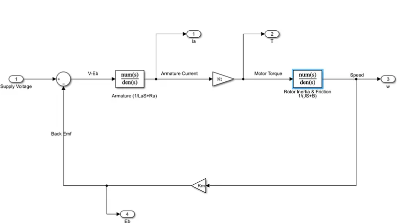
Subsystem: DC_Motor_dynamics
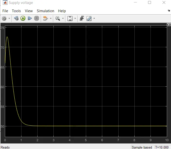
Simulation Results
project_plot.m
subplot(321);plot(out.time,out.Vs);grid;title('Supply voltage in Volts');
subplot(322);plot(out.time,out.Eb);grid;title('Back Emf in Volts');
subplot(323);plot(out.time,out.Ia);grid;title('Armature current in Amperes');
subplot(324);plot(out.time,out.T);grid;title('Motor Torque in N-m');
subplot(325);plot(out.time,out.wc,'b--');grid;title('Speed in radians/s');hold;
subplot(325);plot(out.time,out.w,'m--');
>> project_plot
Current plot held
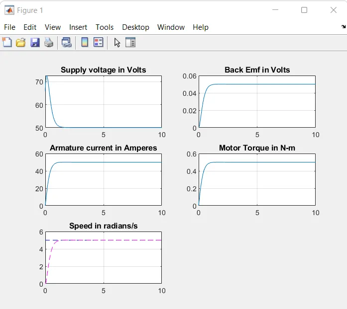
Developed and tested a PID controller to maintain desired speed for the dc motor.