Week-6 Challenge: EV Drivetrain
- Which types of power converter circuits are employed in electric and hybrid electric vehicle?
Power converter circuits employed in electric and hybrid vehicle are:
AC to DC converters (Rectifiers)
- Mainly used in EV chargers
- Rectifiers can be broadly classified as: Controlled rectifiers and Uncontrolled rectifiers
- Controlled rectifiers use controllable switches (whose turn on and turn off can be controlled) for its operation like SCR, IGBT, MOSFET etc. whereas uncontrolled rectifiers use diodes (uncontrollable switch whose turn on and turn off depends on circuit conditions) as the switches.
- Uncontrolled rectifiers are further classified as: half-wave rectifiers and full-wave rectifiers.
- Controlled rectifiers are further classified as: Half wave-controlled rectifiers and full wave-controlled rectifiers. Full wave-controlled rectifiers can be further classified as fully controlled and half controlled rectifiers.
- By controlling the turn on and turn off of switches, we can control the output voltage.
DC to AC converters (Inverters)
- When the electrical energy is supplied by battery and the motor used is AC motor, then we need inverters to convert DC to AC.
- Inverters can be broadly classified as Voltage source inverters and Current source inverters.
- Various Pulse width modulation techniques are employed in inverters to control the output voltage, reduce harmonic content etc
DC to DC Converters (Choppers)
- If the battery used is of 100 V and the vehicle require a DC voltage of 12 V for small power applications like infotainment systems, head lamps etc, we have to convert 100 V DC to 12 V DC. For this purpose, we require a step-down chopper (Buck converter).
- Similarly, there will be applications which require step up of DC voltage. For those applications, we require step-up choppers (Boost converters).
- DC to DC converters can be broadly classified as buck, boost and buck-boost converters.
- Output of these converters can be controlled by controlling the duty cycle.
AC to AC converters (AC voltage controllers)
- These converters are mainly used to convert AC of particular voltage level and frequency to a different voltage level and frequency.
- They are not usually employed in electric vehicles.
2. An Electric Vehicle's powertrain with 72V battery pack in shown in the diagram below. The duty ratio for acceleration operation is 'd1' and for the braking operation the duty ratio is 'd2'.
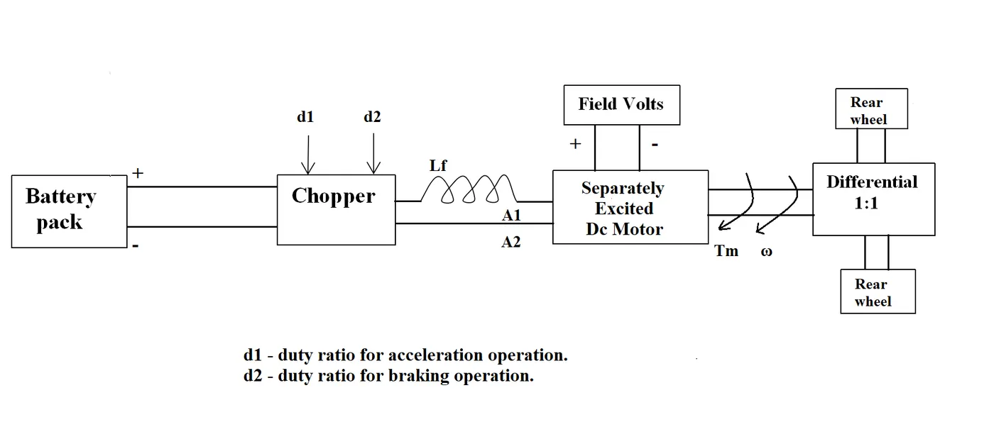
The other parameters of the electric vehicle is given below,
Motor and Controller Parameters:
Rated Armature voltage= 72 V
Rated armature current= 400 A
Ra= 0.5Ω, KΦ= 0.7 Volt second
Chopper Switching frequency= 400 Hz
The vehicle speed-torque characteristics are given by the below equation

What is EV steady state speed if duty cycle is 70%?
The torque-speed characteristics of the electric vehicle is given by
Tv = 24.7 + (0.0051)w2 …………………………(1)
We know that motor torque is given by,
Tm = (KV/Ra) – (K2*w)/Ra ………………………….(2)
Since duty cycle = 70%,
V = 0.7 * 72 = 50.4 V
Given, K = 0.7 and Ra = 0.5 Ω
Substituting the above values in equation (2) we have
Tm = (0.7*50.4)/0.5 – ((0.7^2)*w)/0.5
Tm = 70.56 – 0.98w …………………………..(3)
At steady state,
Tm = Tv
(0.7*50.4)/0.5 – ((0.7^2)*w)/0.5 = 24.7 + (0.0051)w2
0.0051w2 + 0.98w – 45.86 = 0
Solving, we have
w = 38.915 rad/sec 0r w = -231.072 rad/sec
Choosing positive value for w, we have
w = 38.915 rad/sec
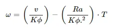
3. Develop a mathematical model of a DC Motor for the below equation using Simulink.
ωω= V/Kϕϕ -Ra/Kϕϕ^2 .T
The mathematical model is developed with given parameters
V = 72 V
Kphi = 0.7
Ra = 0.5 ohm
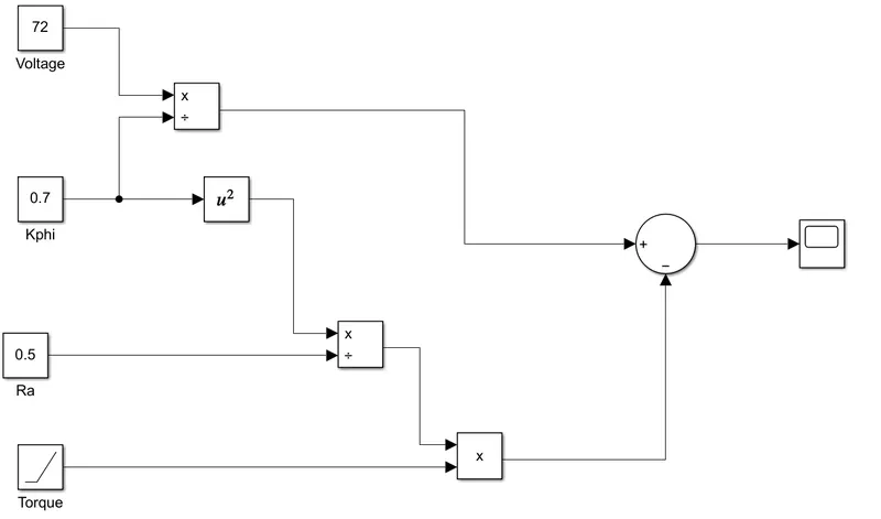
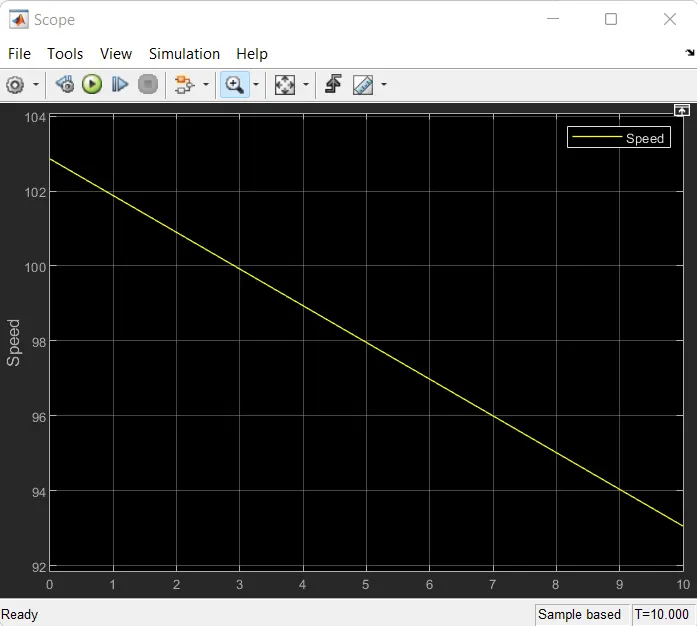
The scope output is given below:
4. Refer to the blog on below topic:
Induction Versus DC brushless motors by Wally Rippel, Tesla
Explain in brief about author’s perspective.
According to author’s perspective, there is no one best motor type, rather there are different types of motor types to suit personal requirements, such as price and performance.
In the past, there were lead acid batteries, DC brush motors, and contactor controllers. But in today’s world, lead acid batteries are replaced by lithium batteries and DC motor by either BLDC or induction motors. Contactors, on the other hand have given way to modulating inverters.
The rotor of BLDC motor includes two or more permanent magnets and as the rotor rotates, it is necessary to vary the magnitude and polarity of the stator currents with the help of an inverter such that torque remains constant and energy conversion is optimally efficient. Without inverters BLDC motors are useless.
The stator of the two machines is identical but the rotors are not. Instead of permanent magnet rotor, the induction motors have squirrel cage rotor. Unlike a BLDC motor, induction motors are directly compatible with conventional utility power and there is no requirement of the inverter. Since the shaft speed is proportionate to line frequency, when used with utility power, they are constant speed machines.
But the induction motor operated in this way have limited starting torque and somewhat limited running peak torque capabilities, when compared to DC type machines.
One of the severe limitations of induction motor is that it cannot be operated from DC. By adding an inverter, it becomes possible to power the machine from a dc source. But still torque performance is low compared with DC machines. By the addition of some feedback loops, the inverter can produce the exact frequency desired by the motor and induction motors are now capable of competing with DC and DC brushless for vehicle applications.
In case of BLDC motors, much less rotor heat is generated, rotor cooling is easier and peak point efficiency is generally higher than induction motors. Moreover, DC brushless drive can also operate at unity power factor, whereas the best power factor for the induction drive is about 85 percent and hence the peak point energy efficiency for a DC brushless drive will typically be a few percentage points higher than for an induction drive.
Ideally, the magnetic flux density should be adjusted that losses are minimized. The magnetic flux density cannot be easily changed in a BLDC motor. In contrast, the induction machine when operated with a smart inverter has reduced magnetic and conduction losses and the efficiency is optimized.
This advantage becomes increasingly important as performance is increased. With DC brushless, as machine size grows, the magnetic losses increase proportionately and part load efficiency drops. With induction, as machine size grows, losses do not necessarily grow. Thus, induction drives may be the favored approach where high-performance is desired; peak efficiency will be a little less than with DC brushless, but average efficiency may actually be better.
Induction motors will likely retain a cost advantage over PM machines but they are more difficult to control. The control laws are more complex and difficult to understand. Achieving stability over the entire torque-speed range and over temperature is more difficult with induction than with DC brushless. This means added development costs, but likely little or no recurring costs.
Hence it is concluded that DC brushless drives will likely continue to dominate in the hybrid and coming plug-in hybrid markets, and that induction drives will likely maintain dominance for the high-performance pure electrics. As hybrids become more electrically intensive and as their performance levels increase, we will see induction and DC brushless live and work side by side during the coming golden era of hybrid and electric vehicles.