Simulating and comparing DC Motor Control using BJT H-bridge, four Quadrant Chopper DC drive, and two-quadrant chopper.
1. A. Explain a MATLAB demo model named ‘Speed control of a DC motor using BJT H-bridge’.
The model demonstrates how the H-bridge is used to generate a chopped voltage and also control the speed of the DC motor. A bipolar Junction Transistor (BJT) is a transistor type which acts as a switch in this case. The H-bridge allows to control both the speed of the DC motor , and also the direction of rotation of the DC motor.
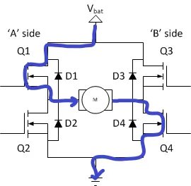
The H-bridge consists of four BJT and diode pairs (Q1,Q2,Q3,Q4 and D1,D2,D3,D4). Two transistors are switched ON simultaneously : Q1 and Q4 together and then Q2 and Q3 together. The BJTs on the same side of the motor are not switched ON simultaneously in order to prevent short circuiting.
When Q1 and Q4 are ON, the positive voltage is applied to the motor, and the current flow is from the positive terminal of the battery to Q1, and then goes to the ground thorough Q4, thereby allowing the flow of current in direction which rotates the motor in the forward direction. During this operation the D2 and D3 diodes are operating as free wheeling diodes. At this stage of operation the Q2 and Q3 are kept OFF, in order to prevent short circuiting.
Reference : https://www.modularcircuits.com/blog/articles/h-bridge-secrets/h-bridges-the-basics/
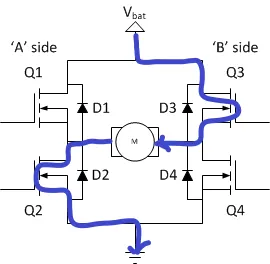
Similarly when the Q2 and Q3 are ON, the other two transistors are maintained in OFF position. In this case the power flow is from the positve terminal of the battery to the Q3 transistor, and then to the motor, from there the power flows through Q2 to the ground, as shown in the diagram. This direction of current flow rotates the motor in the opposite direction, this case called as reverse motoring. In this case the D1 and D4 diodes are operating as free wheeling diodes.
Reference : https://www.modularcircuits.com/blog/articles/h-bridge-secrets/h-bridges-the-basics/
The speed of the DC motors is controlled using the armature voltage control.
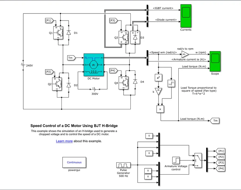
The transistor switches are controlled by an signal, which is generated using the pulse generator. In this simulation, the pulse being generated has an amplitude of 1 unit, time period of 0.002 seconds and a pulse width of 75% ( average DC voltage is 180V), this makes the duty cycle to be 75%. The model devloped as shown below, is simulated for 1 second, wherein for the first 0.5 seconds the voltage is positive, and for the remaining 0.5 seconds, the armature voltage is suddenly reversed and the motor will then begin to rotate in the reverse direction.
Reference : https://in.mathworks.com/help/physmod/sps/ug/speed-control-of-a-dc-motor-using-bjt-h-bridge.html
The output results are as shown below :
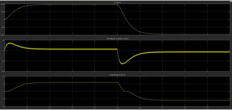
- Speed, armature current and load torque : The speed initially rises from 0 to about 900RPM, reaches steady state, and then after 0.5 seconds the direction changes and the motor RPM reaches steady state at around -900RPM. The armature current also has a similar inference, with positive current in the first 0.5 seconds, and then for the remaining 0.5 seconds of the simulation, the transistors switches changes position, and the current also changes direction.
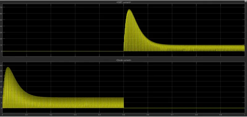
- Q3 and D3 current : It can be observed that for the first 0.5 seoconds, the current is flowing through D3 during forward motoring, and then for the next 0.5 seconds, the current is through Q3, which enables reverse motoring of the motor, which reverses the direction of rotation of the motor. In both the cases, the current in the diode and the IGBT, increases sharply at the starts, and then reaches a steady state after around 0.15 seconds of initiation.
B. Comment on the armature current shoot-up from the scope results.
In DC motors, the back EMF generated is directly proportional to the speed of the motor. During the starting phase, the speed rises slowly, and hence hte back EMF generated is also very small. The internal resistance of the motors are also smaller in magnitude. The equation for DC motors is as shown below :
`V- E_b = I_a*R_a`
In this case, since `E_b`(back EMF) is small and also `R_a`(internal resistance) is small, the armature current `I_a` is very high during the startup of the motor. This is the cause for the sudden shoot up or peak in the result. This can be controlled by reducing the armature voltage. The armature voltage is in turn reduced by reducing the duty cycle. At 75% duty cycle, the average DC voltage is 180V, this value is reduced by reducing the duty cycle.
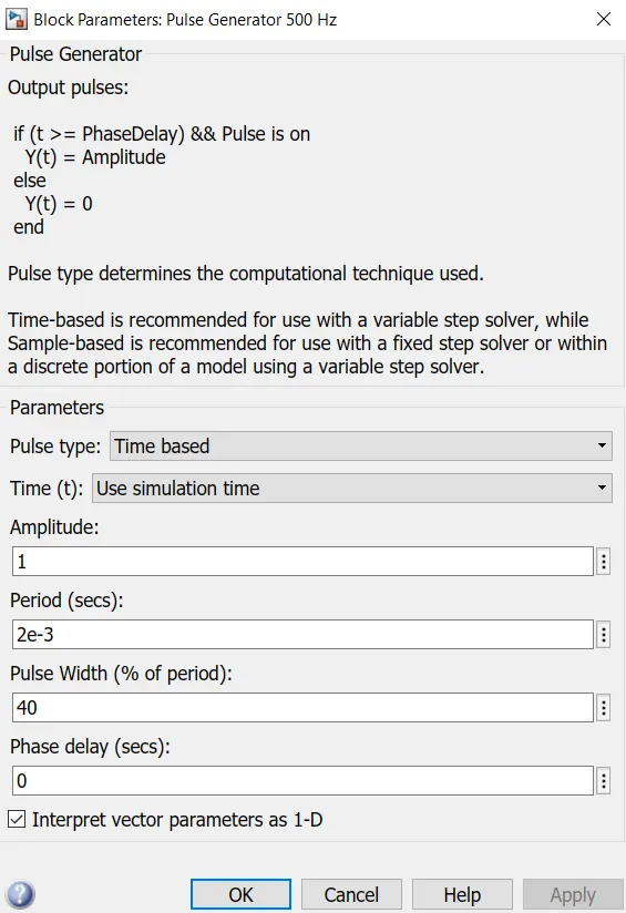
The armature current smoothen at a duty cycle of 40%, at which point the average DC Voltage is 96V. The armature current plot when duty cycle is reduced to 40% are as follows :
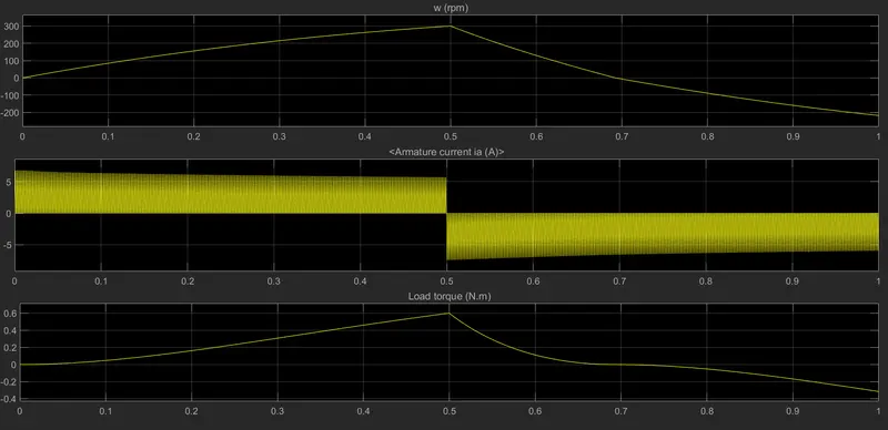
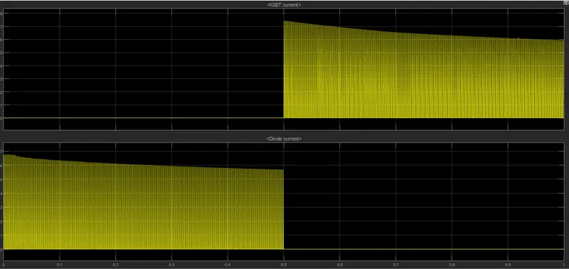
It can be noted that as the duty cycle reduces , the initial current shoot-up reduces, but even the speed of the motor also reduces, as the speed is being controlled by varying the armature voltage. The current through diode D3 and Q3 transistor is also smoothen due to reduced voltage, as shown below.
C. Refer to the help section of ‘The Four-Quadrant Chopper DC Drive (DC7) block’. Compare it with the H-bridge model.
The four quadrant chopper DC drive (DC7) block represents a four-quadrant, DC-supplied chopper drive used for DC motors. The model is used the control the DC motor in all four quadrants of operations namely - forward motoring, reverse motoring, forward regeneration, and reverse regeneration. The DC7 block has a closed loop speed control, wherein the speed regulator outputs the armature current reference used by the current controller in order to obtain the electromagnetic torque needed to produce the requried speed. The current regulator controls the armature current by computing the appropriate duty ratios of the pulse of all the four IGBT devices. The current controller is a simple PI controller, from which the duty cycle corresponding to the required armature current is derived. This duty cycle is then compared with the sawtooth carrier signal to obtain the PWM signals for the chopper.
Reference : https://in.mathworks.com/help/physmod/sps/powersys/ref/fourquadrantchopperdcdrive.html
On comparing with the H-bridge, the main differences are as follows :
- The DC7 block operates the DC motor is all four quadrants, whereas the H-bridge only operates in two quadrants namely forward motoring and reverse motoring. So in the four quadrant DC drive, regenerative braking is possible, while it cannot be done using a H-bridge drive.
- The drive features a closed loop speed control. There are two PI controllers for speed and current regulation. The duty cycle is varied depending on the required speed. The H-beidge on the other hand has a open-loop control, and the pulse width is constant.
- The armature current oscillations and shoot-ups are reduced by a smoothing inductance connected in series with the armature circuit, whereas in H-bridge model, armature current shoot-ups were observed, which had to be reduced by reducing the duty cycle.
- Discretization of the model is done during hte simulation of the DC7 block model, whereas continuous type computation is performed on the H-bridge model. The powergui block is continuous in H-bridge based DC motor speed control, while the discrete computation is performed in the four quadrant chopper DC drive model.
2. Develop a 2-quadrant chopper using simulink & explain the working of the same with the relevant results.
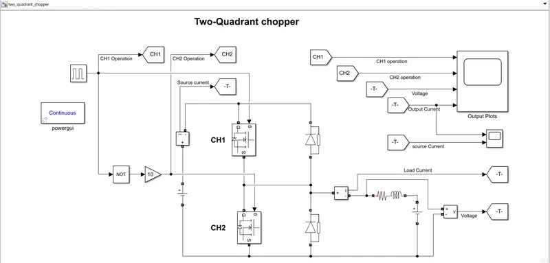
This type of chopper drive provides forward motoring and forward braking. The voltage always remains positive, while the current is positive during forward motoring and negative during forward braking. The simulink model developed is as follows :
Simulink model google drive link : https://drive.google.com/file/d/1EvVp1Y94BFGnuHqcWp0zrCtzFuIDziQF/view?usp=sharing
The two-quadrant chopper consists of two choppers namely CH1 and CH2, and two diodes D1 and D2. The simplified model of the DC motor is represneted with an inductor and voltage source, in some cases the internal resistance can also be included. There are two operating modes:
- Forward Motoring mode : When the chopper CH1 is ON, the voltage flow is from the source to the load (motor). The supply voltage is fed into the motor armature terminals, and hence the armature current increases. The current and voltage are positive and hence the motor rotates in the forward direction. When CH1 is OFF, the armature current freewheels through diode D1, and hence decreases. This entire operation is a first quadrant operation.
- Forward Braking mode: When chopper CH2 is ON, the motor acts a generator and the armature current increases in the opposite direction. Due to this the energy is stored in the inductor. When CH2 is OFF, the diode D2 is turned ON and therefore the armature current is reversed. In this case the voltage is positive, while the current is negative, hence is a second quadrant operation. It is also called as the forward regenerative braking mode. In this case, there is no current flowing through the source, hence the source current is zero.
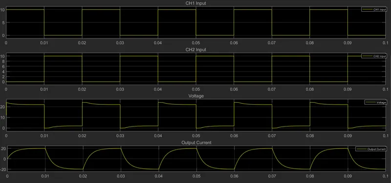
The model is simulated using a pulse input of amplitude equal to 10 units, duty cycle of 50%, and a time period of 0.02 seconds. The model is simulated for 0.1 seconds alone, inorder to view the waveform clearly.
Output plots :
The plots are on CH1 gate input, CH2 gate input , Output voltage, and output current respectively.
The output current and source current waveforms are as follows:
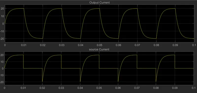
When CH1 is ON, the output or load current increases from 0 to its max-value. When D1 is ON, the current begins freewheeling and also reducing to 0. When CH2 is ON, the current goes from 0 to min-value (negative), and then when D2 is ON, it increases from the min-value and moves towards 0. On the other hand, the source current is zero for the duration when the CH2 is ON, in the remaining part, it is similar to that of the output current.
3. Explain in a brief about operation of BLDC motor.
Brushless DC motor (BLDC) are basically brushed DC motors with electronic commutators. These electronic communtators are nothing but power converters. In BLDC motors have a permanent magnet rotor, and a stator with electric windings. These current carrying windings are fixed as they are around the stator while the rotor rotates.
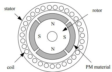
The basic principle is that whenever a current carrying conductor is placed in a magnetic field it experiences a force, and as a consequence of reaction force, the magnet will experience an equal and opposite force. In this case the current carrying conductor is stationary and the magnet is rotating.
Stator windings are connected to a integrated switching circuits, which decides and energizes the proper windings at a proper time, in such a pattern that it makes the rotor rotate. The energising of the windings is dependent on the position of the rotor, which is measured using hall effect sensors. The supply given is DC, but the switching generates a AC waveform.
By switching the correspinding windings, the stator energises as north and south pole, and produces a uniform field in the air gap. The rotor being a permanent magnet tries to align its north and south poles with the energized electromnagnet (stator), and as soon as it align, that pair of stator windings is de-energised and the next pair of stator windings are energised, thus causing the rotor to rotate further. This keeps the rotor rotating continuously. The stator windings are energised in a particular sequence in order to rotate the motor.