Selection of Springs and Anti-roll bar to meet vehicle level targets.
Excel file link : https://drive.google.com/file/d/1gApZI-DvcbSHQZIA6vMBqv5uCvO4d9Pr/view?usp=sharing
Goal of the project:
Select springs and anti-roll bars, and set up swing arm geometry to meet targets for ride frequency, roll gradient and pitch gradient, while staying within certain constraints . The project deals with a 4WD Sedan with MCPherson strut suspension in the front and a multilink setup in the rear.
The project can be divided broadly into three different analysis parts :
- Ride analysis
- Roll analysis
- Pitch analysis
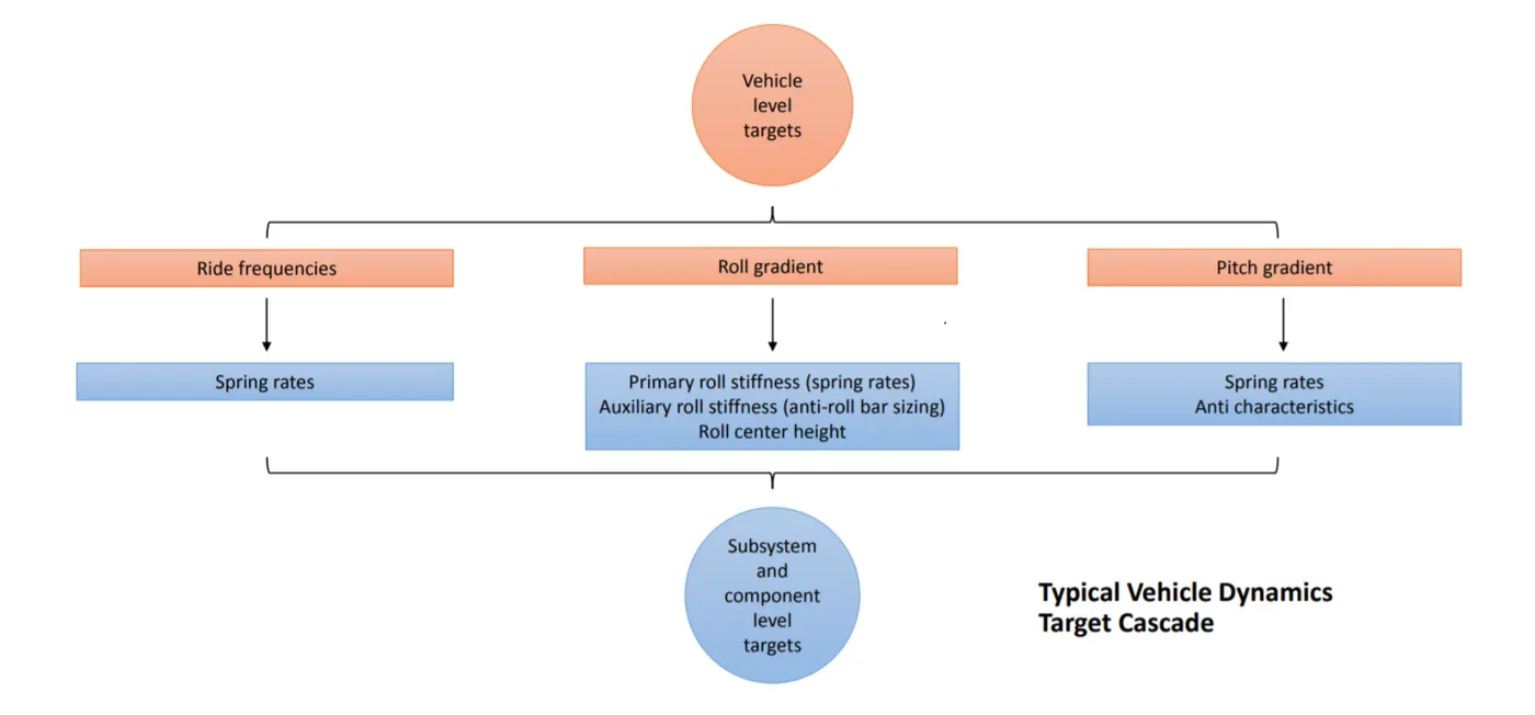
All the three analysis is dependent on one another and hence the process becomes iterative as for example the spring rate satisfying one target might not satisfy another vehicle level target. The spring rates have to selected in such a manner that they satisfy all the vehicle level targets. Further the Anti-roll bar sizes have to be determined by keeping the constraints under check.The following figure depicts the typical vehicle dynamics target cascade.
The derivables are the following parameters:
• Spring rates (front and rear)
• Roll bar diameters (front and rear)
• Rear ride frequency and flat ride plot (at 65 mph)
• Anti characteristics (front and rear - in terms of percentages and instant center locations)
The vehicle level targets and constraints are as follows :
| Target | Values |
| Front ride frequency | 1.35 Hz |
| Roll gradient | 3.80 deg/g |
| Acceleration pitch gradient | 2.00 deg/g |
| Braking pitch gradient | 1.00 deg/g |
The constraints include :
- Max. allowed front auxiliary roll stiffness = 60%
- Max. allowed rear auxillary roll stiffness = 30%
Ride Analysis :
The spring rates can be decided based on the ride frequencies. The ride frequency is defined to be the undamped natural frequency of the body in ride. The higher the frequency, the stiffer the ride.
The rear ride frequency has to be tuned based on the wheelbase and the velocity of the vehicle. When a vehicle goes over a bump, the front suspension comes in contact first and then the rear wheels hits the bump. There is a time lag between when the front wheel and the rear wheel hits the bump. This causes an out-of-phase motion and this causes a pitching motion. So to prevent it, the rear suspension has to catch up with the front suspension, and that is possible by increasing the rear ride frequency. Hence to obtain a flat ride, the rear ride frequency has to be greater than the front ride frequency.
In this case we start with a given ride frequency and then tune the rear ride frequency such that we get a flat ride. For this we start with calculating the time lag based on wheelbase and velocity.
`timelag(s)=(Wheelbase(m))/(velocity(m/s))` The timelag is denoted as `t_(wb).`
As the starting point the rear frequency is calculated from the front ride frequency and the time lag.
`f_r=1/((1/f_f)-t_(wb))`
Where `f_r` is the rear ride frequency and `f_f` is the front ride frequency. ` Further the rear ride frequency is tuned to obtain a flat ride. The front and the rear amplitudes are given by the following equations :
`Frontamplitude=e^-tsin(omegat)=e^-tsin(2πf_ft)`
`Rearamplitude=e^-tsin(omega(t-t_(wb)))=e^-tsin(2πf_r(t-t_(wb)))`
The rear has to catch up with the front within the initial 1-15 seconds. Beyond that the amplitude reduces and the dampers control the further pitching. The graphical representation of the flat ride concept is as shown in figure 1.
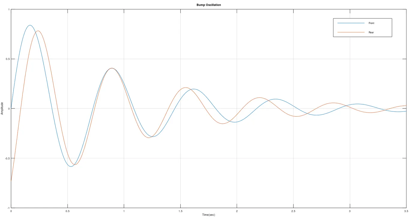
Figure 1: It shows the bump oscillation curve for a front ride frequency of 1.38Hz and the rear ride frequency of 1.53Hz. It can be seen that the oscillations of the front and rear catch up before 1 second.
Once the ride frequencies are chosen, the spring rate needed can be determined from the motion ratio of the suspension, sprung mass supported by each wheel. The basic equation used to calculate the ride rates and wheel rates are mentioned below :
`k_r=4π^2f_f^2m_s`
`k_w=(k_(tire)*k_r)/(k_(tire)-k_r)`
Where `k_r` is the ride rate ,`k_(tire)` is the tire rate, `m_s`is the sprun mass and `k_w` is the wheel rate.
The spring rates can be calculated as :
`k_s=k_w*MR^2`
Where `k_s` is the spring rate and `MR` is the motion ratio.
The spring rates are decided in this ride analysis. Based on the calculated the spring rates are as follows:
Front spring rate = 208.432 lb/in
Rear spring rate = 274.502 lb/in
Roll Analysis :
From the springs rates the primary roll stiffness at the front and rear is calculated. Based on the roll gradient target given , the roll stiffness contribution due to anti-roll bar is calculated. It must be made sure that the percentage of auxillary roll stiffness( Anti-roll bar) is within the constraint limits. If not the primary roll stiffness has to be tuned, which is done by changing the spring rates, but while keeping the target of the front ride frequency in check. Then based on the auxillary stiffness, the anti-roll bar diameter is calculated.
When a vehicle encounter a corner, a lateral load transfer occurs due to the lateral acceleration experienced during cornering. The total load transfer has three components - lateral load transfer due to unpsrung mass. lateral load transfer from direct lateral force and lateral load transfer due to body roll.
Lateral load transfer due to unpsrung mass = `LLT_(unsprung) = (W_(us)⋅Z_(us))/t`
Lateral load transfer due to direct lateral force = `LLT_(sprung)=(W_s*Z_(rc)*(l-x))/(t*l)`
Where `W_s` is the sprung mass, `W_(us)` is the unsprung mass, `Z_(us)` is the CG height of the unsprung mass, `t` is the trackwidth, `Z_(rc)` is the height of the roll centre and `l` is the wheelbase of the vehicle.
Lateral load transfer due to body roll = `LLT_(bodyroll) = (k_(phia)*W_s*h_(arm))/(t*(k_(phif)+k_(phir)-(W_s*h_(arm)))`
The total lateral load transfer = `TotalLLT = (deltaW)/A_y=(W*h)/t` We add 5% of Total lateral load transfer to this as mentioned . This extra 5% of TLLT is to induce understeer in the vehicle.
Where `k_(phia)` is the roll stiffness in that particular axle(front or rear). `k_(phif)` is the front roll stiffness , `k_(phir)` is the rear roll stiffness, `h_(arm)` is the torque arm length and `h` is the CG height.
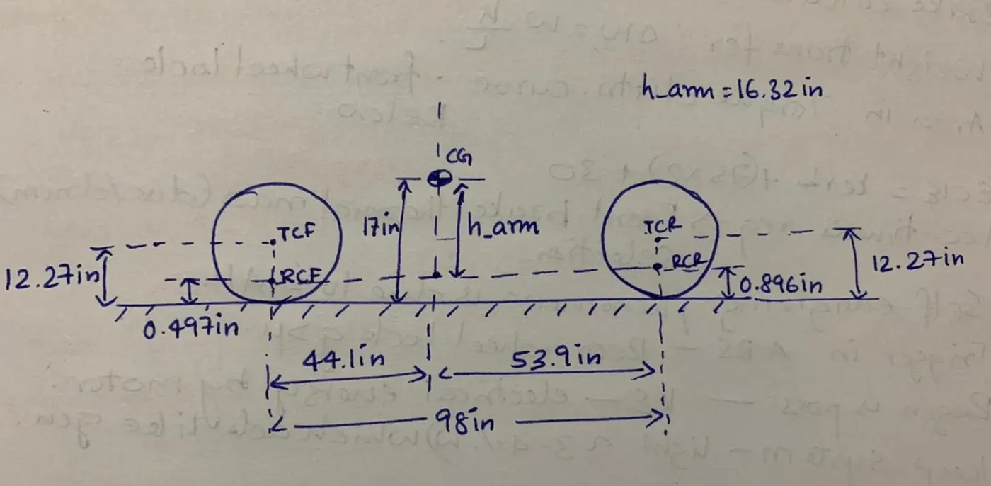
The h_arm is calculated by using the following equation :
`h_(arm)=h-Z_(rcf)-((a_s/l)⋅(Z_(rcr)-Z_(rcf)))`
Where `Z_(rcf)` is the front roll centre height, `Z_(rcr)` is the rear roll centre height and `a_s` is the longitudinal distance between the CG point and front axle.
The total lateral load transfer equation is given by :
`(W*h)/t=((W_(ua)*Z_(us))/t)+(W_s*Z_(rc)*(l-x))/(t*l)+((k_(phia)*W_s*h_(arm))/(t*(k_(phif)+k_(phir)-(W_s*h_(arm)))))`
The total lateral load transfer is obtained from vehicle weight, CG-height and trackwidth. Then the lateral load transfer component is subtracted by the lateral load transfer components due to sprung and unsprung mass. Then we get the lateral load transfer due to body roll.
`LLT_(bodyroll) = TotalLLT - LLT_(unsprung) - LLT_(sprung)`
We already know from the previous equations that : `LLT_(bodyroll)=(k_(phia)*W_s*h_(arm))/(t*(k_(phif)+k_(phir)-(W_s*h_(arm)))) = (k_(phia)*phi)/t`
Where `phi` is the roll gradient which is one of the vehicle level targets.
From the above calculation steps the front roll stiffness is found. Further the total vehicle roll stiffness is calculated and then rear roll stiffness can be calculated based on the below mentioned equations.
Roll moment = `M_(phi)=k_(phi)*phi`Where `M_phi` is the roll moment and `k_phi` is the total roll stiffness. The total roll stiffness is equal to the sum of front and rear roll stiffness.
The roll moment has two components, namely the lateral component and then a gravity component.
Roll moment =`M_phi=W_s*h_(arm)*A_y*cos(phi) + W_s*A_y*h_(arm)*sin(phi)`. For small angles `cos(phi)=1 and sin(phi) = phi` Further substituting this the total roll moment is calculated.
Rearranging the set of equation we get :`k_phi = (W_s*h_(arm) + W_s*h_(arm)*phi)/phi`
The front and rear roll stiffness are henceforth calculated. This stiffness is the combined stiffness of the tires, spring and the anti-roll bar. The roll stiffness contribution by the springs are called the primary stiffness and the roll stiffness contributed by the anti-roll bar is called as the auxillary stiffness. The contribution of the tire has to be isolated. Figure below represents the contributions to roll stiffness clearly.
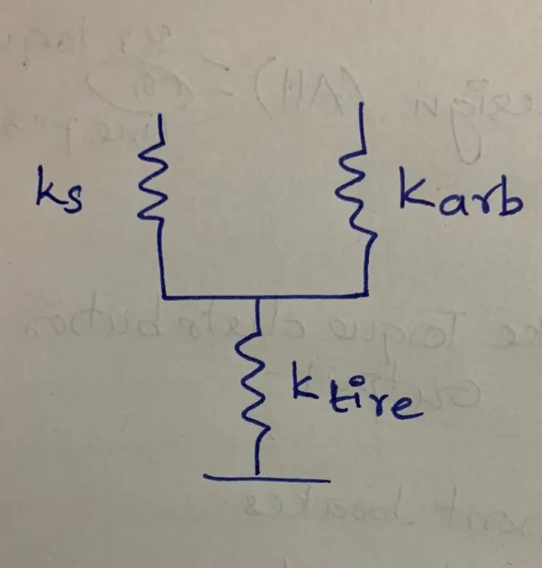
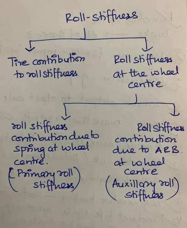
The general equation for the above setup is : `1/k_(phif) = (1/k_(phiwc)+1/k_(phitire)).`
The front roll stiffness at the wheel centre is given by : `k_(phiwc) = (k_(phitire)*k_(phif))/(k_(phitire) - K_(phif))`
The front roll stiffness at the wheel centre is a sum of the roll stiffness due to springs and the anti-roll bars.
`k_(phiwc) = k_(phis) + k_(phiarb)`.
Where `k_(phis)` is the roll stiffness contribution / primary stiffness at the wheel centre. While `k_(phiarb)` is the roll stiffness contribution due to anti-roll bar / auxillary stiffness at the wheel centre. The primary stiffness can be calculated using the below mentioned equation.
`k_(phis) = (k_s*t^2*MR^2)/2`
Further auxillary stiffness can be calculated : `k_(phiwc) - k_(phis) = k_(phiarb)`
The contribution of the auxillary stiffness is checked at the front and rear, as it must not go beyond the contraint limits.
The primary roll stiffness (%) is given by : `(k_(phis)/k_(phif))*100`
Similarly the auxillary roll stiffness (%) is given by : `(k_(phiarb)/k_(phif))*100`
Once the percentage is within the constraints the anti-roll bar is then designed for this auxillary stiffness. If not the percentage contriubution of primary roll stiffness is increased, so the percentage contribution by the auxillary stiffness will reduce. This can be done by changing the spring ride rates. Again ride analysis will have to be performed to meet the targets of both the ride and roll analysis keeping the constraints under check.
In the design proposed under this project, the maximum auxillary stiffness (%) at the front is 59.04% (which is <60%) and the maximum auxillary stiffness(%) at the rear is 15.96% ( which is <30%).
Design of anti-roll bar: The diameter of the ARB( anti-roll bar) can be calculated from the below mentioned equation.
`k_(phiarb) =( 500000*(OD)^4)/((0.4422*A^2⋅B) + (0.2264*C^3))*2*MR^2*(t^2/2)`
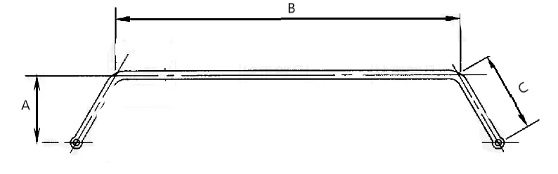
In this case we are considering the ID = 0. OD is the outer diameter (in), 'A' is the virtual torque arm(in), 'B' is the central length (in) and 'C' is the physical torque arm(in), 't' is the vehicle trackwidth(in) and kϕarb">kϕarbkϕarb is the auxillary stiffness (in-lb/deg).
In this case the case the outer diameter of the anti-roll bar in the front is 22.28mm and the outer diameter in the rear is 12.64mm.
Pitch Analysis :
Pitching is the shift of the vehicle weight forwards or backwards as a result of braking and accleration respectively. Pitch angle is the angle that the body of the vehicle makes with the horizontal. When the vehicle acclerates there a net weight transfer to the rear from the front, and this causes the rear end of the vehicle to point downwards, this is called as squat. Whereas while hard braking, the weight transfers from the rear to the front, causing the vehicle to point downwards in the front side, this is called as dive. This resulting pitching action affects the ride handling and comfort. So the anti-characteristics can be used to reduce or completely eliminate the vehicle pitching motion.
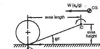
Anti-characteristics is the geometry which uses the horizontal forces to eliminate or reduce the spring deflection caused due to the vertical load transfer. The anti-characteristics includes:
- Anti-dive : Reduces the compression travel in the front suspension during braking.
- Anti-squat : Reduces the compression travel in the rear suspension dueing acceleration.
- Anti-lift : Reduces the rebound action of the front suspension during acceleration and rear suspension during braking.
The anti-characteristics are based on the swing arm geometry, position of the instant centre, and the distribution of traction and braking forces. So to start of the pitch angle without compensation is calculated and then the swing arm geometry is appropriately designed to achieve the required accleration pitch gradient and braking pitch gradient. If there is no anti-features, the pitch angle is the function of load transfer and wheel rate.
Front end deflection without compensation :`Z_f = (deltaW)/(2*k_(rf))`
Rear end deflection without compensation :`Z_r = (deltaW)/(2*k_(rr))`
Where `deltaW` is the net longitudinal load transfer during acceleration and braking. `k_(rf)` is the front ride rate and `k_(rr)` is the rear ride rate. The pitch angle without compensation can be calculated from the deflections.
pitch angle (deg/g) = `((Z_f + Z_r)/l)*(180/pi)`
The vehicle under consideration is a 4WD. So horizontal forces of traction and braking will be there in all wheels. So to achieve the accleration pitch gradient target suitable anti-squat and anti-lift has to be designed for the rear and front suspension respectively. Likewise to achieve the braking pitch gradient target, suitable anti-dive and anti-lift has to be designed for the front and rear suspension respectively.
For tractive forces, the formula for % anti-squat and % anti-lift varies based on whether the suspension is an independent or dependent suspension. The vehicle under consideration has independent suspension both in the front and rear. For the independent suspension, the formula's are as mentioned below :
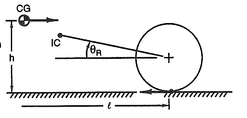 Figure 3: calculation of % anti-squat in the rear suspension
Rear Suspension : % Anti-squat =`(tan(theta_r)/tan(theta_(actual))*(1-phi_(drive)))*100`
where `tan(theta_r) = (e-r)/d` and `tan(theta_(actual)) = h/l`
Where 'e' is the IC-vertical height, 'r' is the tire loaded radius, 'd' is the IC horizontal distance, 'h' is the CG height and 'l' is the wheelbase. ϕdrive">ϕdriveϕdriveis the drive ratio in the front.
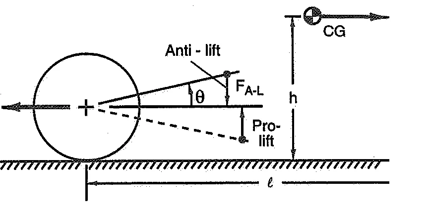 Figure 4 : Calculation of % anti-lift in the front suspension.
Front Suspension : % Anti-lift =`(tan(theta_f)/tan(theta_(actual))*phi_(drive))*100`
where `tan(theta_f) = (e-r)/d` and `tan(theta_(actual)) = h/l`
Where 'e' is the IC-vertical height, 'r' is the tire loaded radius, 'd' is the IC horizontal distance, 'h' is the CG height and 'l' is the wheelbase.
The anti-features reduce the pitching motion. The resulting deflection and acceleration pitch gradient with compensation are as follows:
`Z_(f1) = Z_f*((100-%antiliFt)/100)`
`Z _(r1) = Z_r*((100-%antisquat)/100)`
Acceleration gradient = `((Z_(f1) + Z_(r1))/l)*(180/π)`
Where `Z_(f1)` and `Z_(r1)` is the front and rear end deflection with compensations.
The variables like - IC horizontal distance and IC vertical distance in the front and rear suspension is tuned to arrive at the targetted acceleration pitch gradient which is 2.00deg/g. Likewise for Braking the front %anti-dive and the rear %anti-lift has to be designed to meet the targets of brake pitch gradient.
Front Suspension : % Anti-dive = `(tan(theta_f)/tan(theta_(actual))*phi_(brake))*100`
where `tan(theta_f) = e/d` and `tan(theta_(actual)) = h/l`
Rear Suspension : % Anti-lift = `(tan(theta_f)/tan(theta_(actual))*(1-phi_(brake)))*100`
where `tan(theta_f) = e/d` and `tan(theta_(actual)) = h/l`
The braking pitch gradient is calculated in a similar way as of acceleration pitch gradient. The IC-vertical distance and the IC horizontal distances must be tuned to satisfy both the accleration and braking pitch gradients.
The parameters were tuned to get an accleration pitch gradient equal to 2.004 deg/g and a braking pitch gradient to be 1.004 deg/g.
The front IC horizontal distance is 69 inches and front IC vertical distance is 12.8 inches. While the rear IC horizontal distance is 100 inches and the rear IC vertical distance is 19 inches.
Conclusion:
The spring and anti-roll bars were selected to meet all the vehicle level targets and constraints.
Front ride frequency = 1.38Hz.
Roll gradient = 3.8 deg/g.
Acceleration pitch gradient = 2.004 deg/g
Braking pitch gradient = 1.004 deg/g.
Actual auxillary stiffness in the front is 59.04 %
Actual auxillary stiffness in the rear is 15.96%.
Outputs:
Front spring rate = 208.50 lb/in
Rear spring rate = 274.50 lb/in
Front anti-roll bar diameter = 22.50mm
Rear anti-roll bar diameter = 12.75mm.