Week-7 Challenge: DC Motor Control
1. A. Explain a MATLAB demo model named ‘Speed control of a DC motor using BJT H-bridge’.
B. Comment on the armature current shoot-up from the scope results.
C. Refer to the help section of ‘The Four-Quadrant Chopper DC Drive (DC7) block’. Compare it with the H-bridge model.
Ans. A.). The Speed Control of a DC Motor using BJT H – Bridge is the Simulink model. It's used to generate a chopped voltage and to control the speed of a DC Motor.
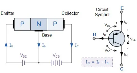
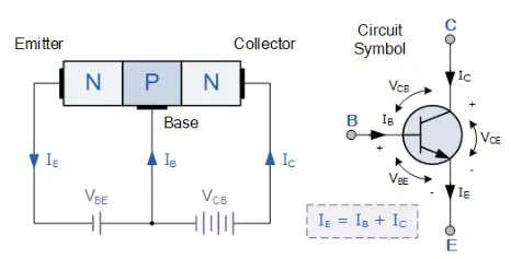
BJTs are 3 terminal devices – Emitter (E), Base (B) & Collector (C). It's of 2 types (i). PNP Transistor and (ii). NPN Transistor.
i. PNP Transistor
Two p-type semiconductors and one n-type semiconductor make up this sort of transistor. The n-type semiconductor serves as the base, while the other two serve as the collector and emitter, respectively. The emitter terminal of the power supply is linked to the negative terminal, whereas the collector terminal is connected to the positive terminal. The base terminal receives voltage and controls the transistor by flipping between ON and OFF states. The transistor is in the OFF state when the base voltage is the same as the emitter voltage, and the transistor is in the ON state when the base voltage is lower than the emitter voltage.
ii. NPN Transistor
Two n-type semiconductors and one p-type semiconductor make up this sort of transistor. The p-type semiconductor serves as the base, while the other two serve as the collector and emitter. The emitter terminal of the power supply is linked to the negative terminal, whereas the collector terminal is connected to the positive terminal. The base terminal receives voltage and controls the transistor by flipping between ON and OFF states. The transistor is in the OFF state when the base voltage is the same as the emitter voltage, and the transistor is in the ON state when the base voltage is lower than the emitter voltage.
BJT H – Bridge
A forward voltage is created between the Collector and the Emitter when the BJT is conducting/operating in the saturated zone. The H-Bridge is made up of two diode pairs and four BJTs (Q1, Q2, Q3, Q4) (D1, D2, D3, D4) respectively.
Positive voltage is provided to the motor when Q1 and Q4 are ignited. The diodes D2 and D3 serve as a Free-Wheeling Diode, while the transistors Q1 and Q4 are turned off.
When Q2 and Q3 are both activated, a negative voltage is supplied to the motor. D1 and D4 will serve as free-wheeling diodes, while Q2 and Q3 will be turned off.
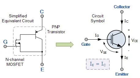
IGBT
Insulated Gate Bipolar Transistor, is a mix of BJT and MOSFET, making it an ideal semiconductor switching device. It has the property of both MOSFET, high input impedance and high switching speed and of BJT, low saturation voltage. So, the IGBT is capable of handling large Collector-Emitter currents with zero gate current drive. The amount of amplification achieved by IGBT is a ratio between its output signal and its input signal.
B.). Armature Current Shoot-Up:
Simulink Model:
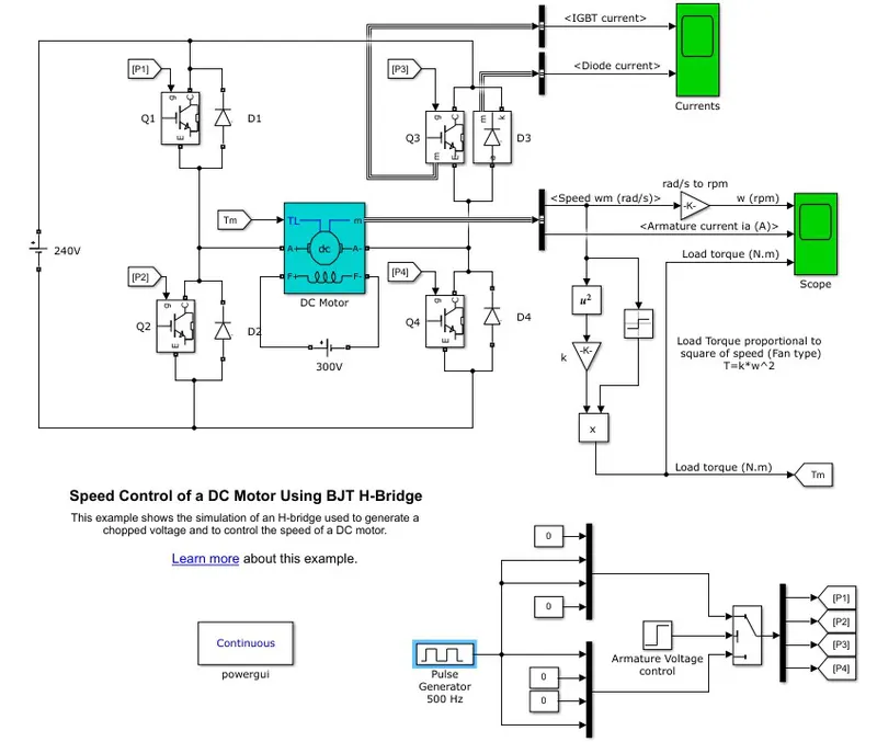
Here, we have a Pulse Width Generator of 500 Hz with preset values of Amplitude of 1, Period of 2 x 10⁻³ secs, Pulse width of 75% and 0-sec phase delay. So, we can modify the duty cycle as per our need and therefore prevent the motor current from overshooting and changing its direction from forward to reverse.
The 75% pulse width means that the motor is receiving the voltage for 75% of the time and would remain off or doesn't receive the voltage for the remaining 25% of the time. So, it'll be ON for 75% of the time and OFF for 25% of the time.
Output for Initial Conditions: (75% Duty cycle)
Initial Condition Current Output Initial Condition Scope Output
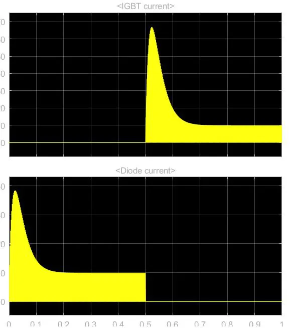
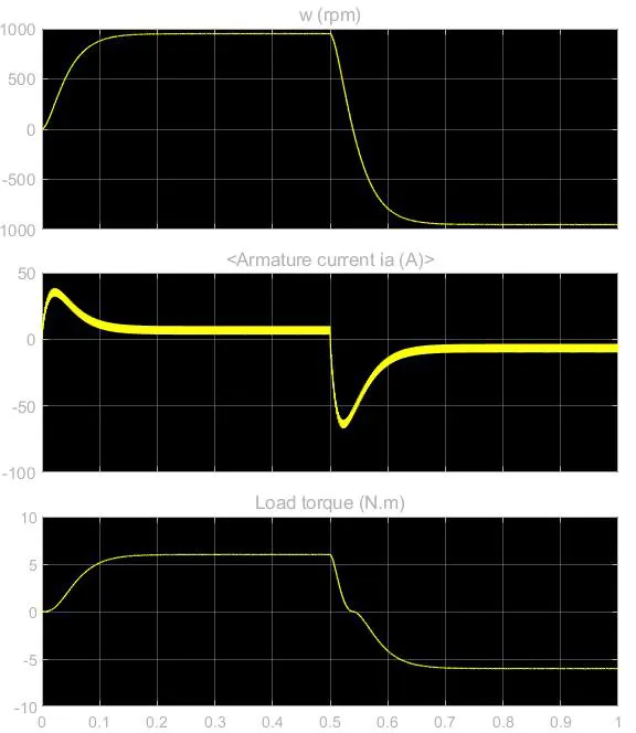
We can see in the current output that the armature current shoots as soon as there is a change in the direction of the motor when the duty cycle is 75%.
So, in order to bring down or lower the armature current, we lower the duty cycle to 50%.
Output for Initial Conditions: (50% Duty cycle)
Initial Condition Current Output Initial Condition Scope Output
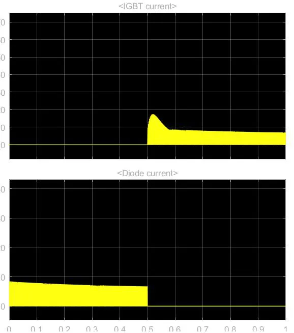
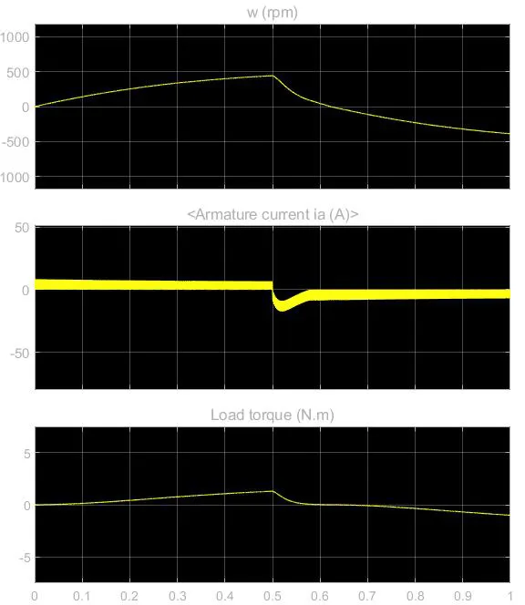
We can see from the output when the duty cycle is 50%. The armature current is lower as compared to the 75% duty cycle. Also, it can be observed that the IGBT Current and the Diode current are also lower when the duty cycle is 50% as in comparison with the 75% duty cycle.
C.). The Four-Quadrant Chopper DC Drive:
The 4 – Quadrant Chopper DC drive block represents a 4 – Quadrant DC supplied chopper drive for DC Motors, also referred to as the DC7 motor drive in SIMSCAPE.
Closed-loop speed control with four-quadrant operation is included. The machine's armature current will be output via the closed-loop speed control. The chopper duty cycle corresponding to the required armature current is calculated using a PI current controller. To produce the appropriate PWM signal for the chopper, the duty cycle is compared to a sawtooth carrier signal.
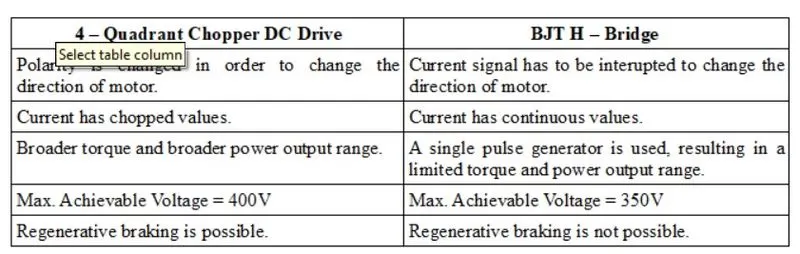
In comparison to the DC Drives, the 4 – Quadrant Chopper DC Drive is more advantageous as it can be operated in all 4 – Quadrants. Each Quadrant has a different set of operations.
1st – Quadrant => Forward Motoring.
2nd – Quadrant => Reverse Braking
3rd – Quadrant => Reverse Motoring
4th – Quadrant => Forward Braking
Also, the 4 – Quadrant Chopper DC Drive uses high-frequency DC-DC converters resulting in a lower armature current ripple. 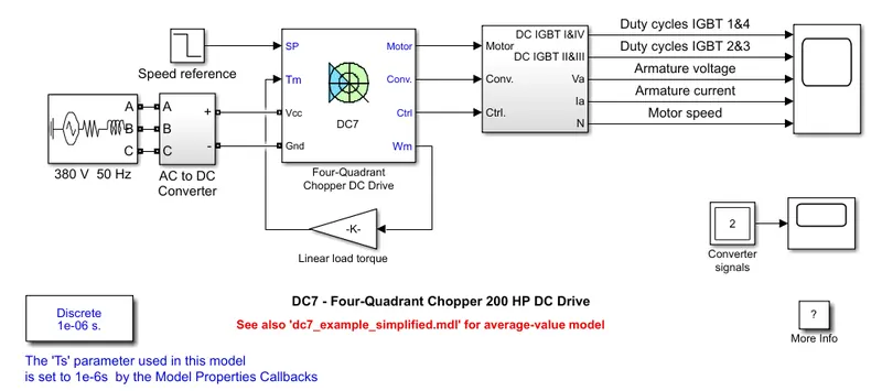
A steady 150V DC field voltage source is used to power the 200HP DC Motor. An IGBT converter provides the armature voltage, which is regulated by two PI converters. A 515V DC Bus is used to power the converter, which is created by rectification of a 380V AC 50Hz voltage source. A brake chopper has been installed between the diode rectifier and the DC7 block to limit the DC bus voltage during dynamic braking mode.
There are two types of regulators: speed and current. The current controller uses the armature current reference provided by the speed regulator to calculate the Electromagnetic Torque required to attain the specified speed. The current regulator, on the other hand, regulates the armature current by determining the necessary duty ratios of the 4 IGBT devices' 5 kHz pulses.
The instantaneous pulse values of IGBT devices 1 and 4 must be opposite those of IGBT devices 2 and 3 for optimum system functioning. This gives you the average armature voltage you'll need to get the armature current you want.
2. Develop a 2-quadrant and Q chopper using Simulink & explain the working of the same with the relevant results.
Ans.
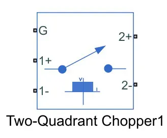
The Two – Quadrant Chopper block represents a 2 – quadrant-controlled chopper for converting a fixed DC input to a variable DC output. The block contains two switching devices. Options for the type of switching devices are:
GTO — Gate turn-off thyristor.
Ideal semiconductor switch
IGBT — Insulated-gate bipolar transistor.
MOSFET — N-channel metal-oxide-semiconductor field-effect transistor.
Thyristor
Averaged Switch.
Simulink model – 1:
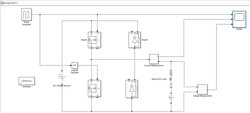
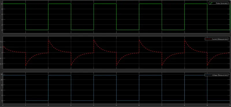
Here, in the simulation, the Pulse Generator block is used to generate gate pulse with parameters Amplitude set to 10, period of 2 seconds and the pulse width of 50%. The DC Voltage source is of 24V, an RLC circuit, that will act as motor load, is connected with series with another DC Voltage source of 12V.
The NOT – Gate is used so that the 2 MOSFETs don't get closed at the same time and cause short-circuit.
Output:
In the output, we can observe that the graph of Pulse Generator and the Voltage Measurement is the same, i.e., square wave. Whereas, there is a sudden change in current whenever there is a change in the pulse generator or the voltage. If the change is decreasing, then the current graph shows a negative increase and when the voltage and pulse are constant, the current slowly comes to zero and vice-versa.
Simulink model – 2:
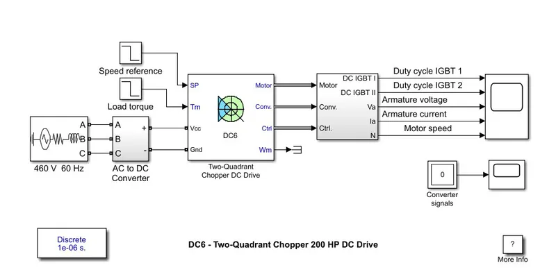
The first regulator is a speed regulator, followed by a current regulator. The speed regulator outputs the armature current reference (in p.u.) used by the current controller in order to obtain the electromagnetic torque needed to reach the desired speed. The speed reference change rate follows acceleration and deceleration ramps in order to avoid sudden reference changes that could cause the armature to over-current and destabilize the system. The current regulatory controls the armature current by computing the appropriate duty ratios of the 5 kHz pulses of the two IGBT devices (Pulse Width Modulation). For proper system behaviour, the two IGBT devices have opposite instantaneous pulse values.
Output:
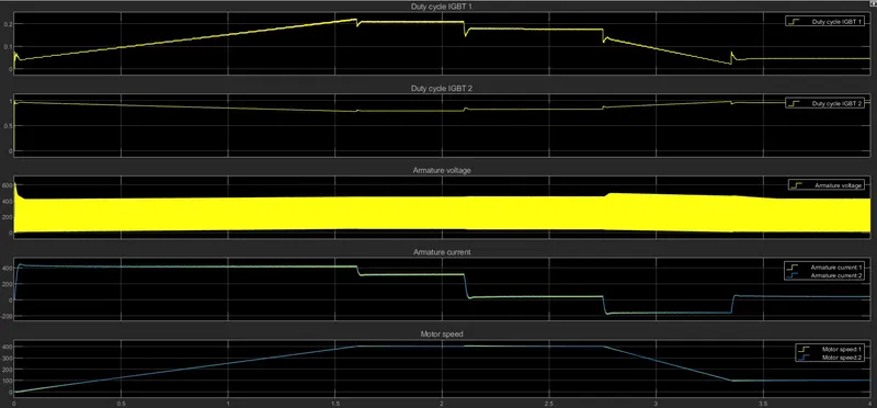
The output of this generates the average armature voltage needed to obtain the desired armature current. In order to limit the amplitude of the current oscillations, a smoothing inductance is placed in series with the armature circuit.
Simulink model – 3:
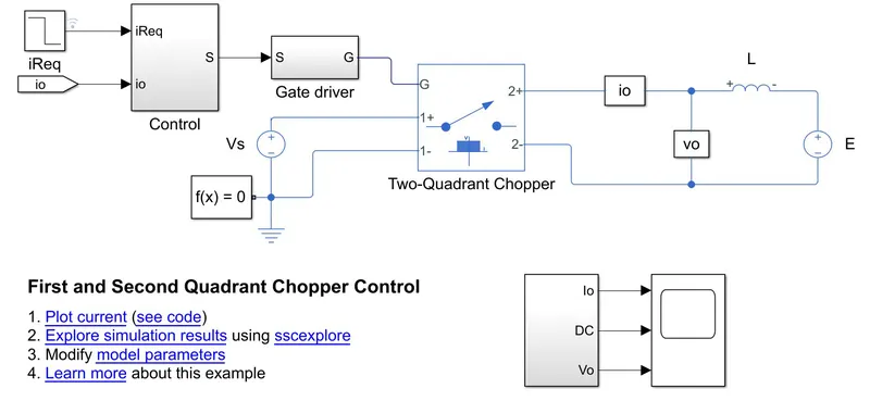
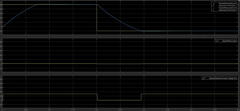
The two-quadrant chopper operates in the first and second quadrants, allowing positive and negative output current. The Control subsystem implements a simple PI-based control algorithm for controlling the output current. The load of the system is considered constant throughout the simulation.
Output:
The plot below shows the requested and measured current for the test and the output voltage in the circuit.
Simulink model – 4:
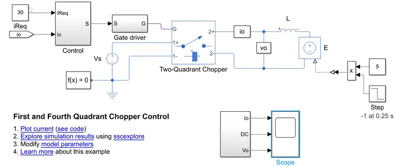
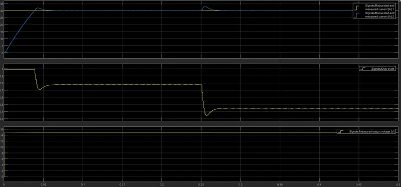
The two-quadrant chopper operates in the first and fourth quadrants, allowing positive and negative output voltage. The Control subsystem implements a simple PI-based control algorithm for controlling the output current. The total simulation time (t) is 0.5 seconds. At t = 0.25 seconds, the polarity of the load DC source E is changed.
Output:
The plot below shows the requested and measured current for the test and the output voltage in the circuit.
However, for any 2 – Quadrant DC drives, the reversible and regenerative operations are concerned, they can't be achieved because of lower Armature current.
3. Explain in brief the operation of the BLDC motor.
Ans. The forerunner of the 3 - phase induction motor was invented by Nikola Tesla sometime before 1889. Curiously, the stators for the 3-phase induction motor and the DC brushless motor are virtually identical. Both have three sets of “distributed windings” that are inserted within the stator core. The essential difference between the two machines is the rotor.
A motor turns electrical energy into mechanical energy when it is provided. Different types of motors are commonly used. Brushless DC motors (BLDC) are a type of motor that has high efficiency and excellent controllability and is widely used in a variety of applications. In comparison to other motor types, the BLDC motor saves energy.
Engineers may consider how electrical impulses are transformed into energy when faced with the job of constructing electrical equipment to accomplish mechanical activities. Actuators and motors are two examples of devices that turn electrical impulses into motion. Electrical energy is converted into mechanical energy by motors.
Common Motor Types
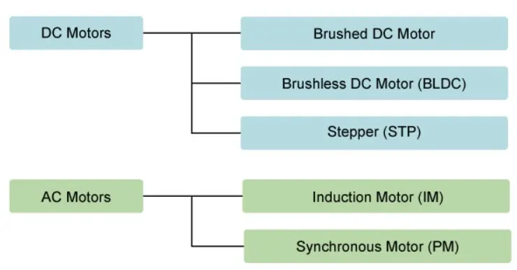
Motors differ according to their power type (AC or DC) and their method for generating rotation (Figure 2). Below, we look briefly at the features and uses of each type.
Brushed DC motors are commonly used to open and close disc trays because of their simple design and ease of control. They are frequently used in automobiles to retract, expand, and position electrically operated side windows. These motors are appropriate for a wide range of applications due to their inexpensive cost. Brushes and commutators, on the other hand, tend to wear out fast as a result of their constant contact, necessitating regular replacement and maintenance.
Brushless DC motors, as their name suggests, do not utilize brushes. Brushed motors use brushes to carry current from the commutator to the rotor's coils. So, how does a brushless motor provide electricity to the rotor coils? Because the coils aren't on the rotor, it doesn't work. Instead, the rotor is a permanent magnet; the coils do not rotate but are instead fixed in place on the stator. Because the coils do not move, there is no need for brushes and a commutator.
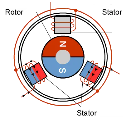
Since the rotor is a permanent magnet, it needs no current, eliminating the need for brushes and commutators. Currently, the fixed coils are controlled from the outside.
Advantages of BLDC Motors
A BLDC motor with three stator coils will have six electrical wires flowing from these coils (two for each coil). Three of these wires will be linked inside in most cases, with the remaining three wires projecting from the motor body (in contrast to the two wires extending from the brushed motor described earlier). Wiring in the BLDC motor casing is more sophisticated than simply connecting the power cell's positive and negative terminals; in the second session of this series, we'll take a closer look at how these motors operate. Finally, we'll take a look at the benefits of BLDC motors.
One significant benefit is efficiency, as these motors can control at maximum rotating force continually (torque). Brushed motors, on the other hand, only attain maximum torque at specific periods during rotation. Larger magnets would be required for a brushed motor to generate the same torque as a brushless motor. As a result, even tiny BLDC motors may provide significant power.
Controllability is the second major benefit, which is linked to the first. BLDC motors may be programmed to produce accurate torque and rotation speed utilizing feedback systems. Precision control, in turn, minimizes energy consumption and heat output, while also extending the battery life in circumstances where motors are driven by batteries.
Due to the lack of brushes, BLDC motors are also very durable and produce very little electric noise. Brushes and commutators wear down in brushed motors as a result of continual moving contact, and sparks are produced when contact is made. The powerful sparks that tend to form in the locations where the brushes travel across the gaps in the commutator cause electrical noise in particular. This is why BLDC motors are frequently recommended in applications where electrical noise is a concern.
Ideal Applications for BLDC Motors
We've seen that BLDC motors have a high level of efficiency and controllability, as well as long service life. So, what exactly are they used for? They are commonly employed in continuous-running equipment because of their efficiency and endurance. They've been used in washing machines, air conditioners, and other consumer gadgets for a long time, and they're now showing up in fans, where their great efficiency has resulted in huge power savings.
They're also utilized to power vacuum cleaners. A modification in the control software resulted in a substantial increase in rotational speed in one case, demonstrating the motors' superior controllability.
BLDC motors are also used to spin hard disc drives, where their durability keeps the drives running reliably over time, while their energy efficiency helps to reduce energy consumption in an area where it is becoming increasingly crucial.
Toward Wider Usage in the Future
In the future, we may expect to see BLDC motors employed in a larger range of applications. They will most likely be used to power service robots, which are tiny robots that provide services in domains other than manufacturing. Stepper motors, where pulses might be utilized to accurately regulate the location, could seem to be a better fit for this sort of application. BLDC motors, on the other hand, are better at managing force. Furthermore, retaining the position of a structure such as a robot arm with a stepper motor would need a rather big and constant current. All that is necessary with a BLDC motor is a current proportional to the external force, allowing for more power-efficient control. BLDC motors may also be replacing simple brushed dc motors in golf carts and mobility carts. In addition to their better efficiency, BLDC motors can also deliver more precise control—which in turn can further extend battery life.
BLDC motors are also ideal for drones. Their ability to deliver precision control makes them especially suited for multirotor drones, where the drone’s attitude is controlled by precisely controlling the rotational speed of each rotor.
Controlling BLDC Motors
BLDC motors have gained considerable attention for their ability to deliver high efficiency in a small package, and for their long service life and excellent controllability. In this session, we look at how we can control them to make effective use of their potential capabilities.
Controlling the Magnetic Field
To rotate a BLDC motor, one needs to control the direction and timing of the current into the coils. The figure illustrates a BLDC motor’s stator (coils) and rotor (permanent magnets). Let’s use this illustration to see how the rotor is made to turn. In this example, we are using three coils, whereas in practice it is more common to use six or more. But here we look at just three coils, spaced at 120º. A motor, as we noted in our last session, performs the task of converting electrical energy into mechanical energy. So how does the motor in our illustration do this? Let’s look at what goes on inside.
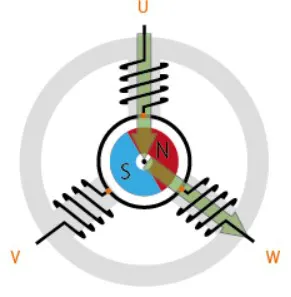
Rotation is maintained by continually switching the flux so that the permanent magnet is constantly chasing the rotating magnetic field induced by the coils. In other words, the energizing of U, V, and W must be continually switched so that the resultant flux keeps moving, producing a rotating field that continually pulls on the rotor magnet.
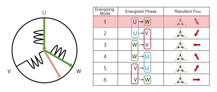
As you can see, switching sequentially through modes 1 through 6 will cause the rotor to turn clockwise through one rotation. The speed of rotation can be controlled by controlling the rate at which the phases change. We use the name “120º conducting control” for the 6-mode control method described here.
Sinusoidal Control Delivers Smooth Rotation
There are just six resulting flux directions for controlling the motor with 120º conducting control. Switching from Mode 1 to 2 for example, shifts the resulting flux direction by 60º, pushing the rotor along with it. Switching from Mode 2 to 3 reverses the flux direction by 60º, pushing the rotor once again. When you repeat this method, you'll have a constant rotation, but it'll be jerky. This jerkiness might cause undesired vibrations and mechanical noise in some circumstances.
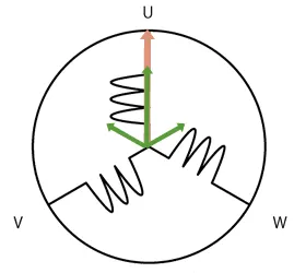
We can get smoother and quieter operation using sinusoidal control instead of 120-degree conducting control. The motor is regulated by cycling through six fixed resultant fluxes continuously with 120-degree conducting control. U and V both produce fluxes of identical size, as seen in Figure. We may produce different flux magnitudes at each coil by carefully manipulating the current entering U, V, and W, allowing us to change the resulting flux with more precision.
Control by Inverter
We may change the amount of the current by utilizing the inverter circuitry to modify the voltage in each coil. Pulse width modulation is a common method of adjusting voltage (PWM). We change the voltage in this method by prolonging or shortening the pulse ON time (also known as the "duty cycle": the ON time expressed as a ratio of the ON+OFF switching interval). Increasing the duty cycle has the same impact as increasing the voltage while decreasing it has the same effect as decreasing the current.
MPUs with specialized PWM circuitry can be used to implement PWM. While 120º conduction control just requires two-phase voltage control and is reasonably simple to implement in software, sinusoidal control requires three-phase voltage control and is much more difficult. In order to drive BLDC motors, proper inverter circuitry is required. Inverters can be used with both AC and DC motors. However, when the word "inverter type" is used in the context of consumer electronics, it typically refers to a BLDC motor.
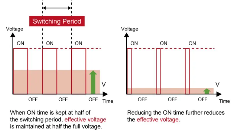
Varying the duty cycle (the ON time within each switching period) changes the effective voltage.
BLDC Motors and Positional Sensors
We operate BLDC motors by constantly altering the directionality of the flux produced by the coils, as we've seen. The rotor turns because the permanent magnets on the rotor pursue the changing spinning magnetic field.
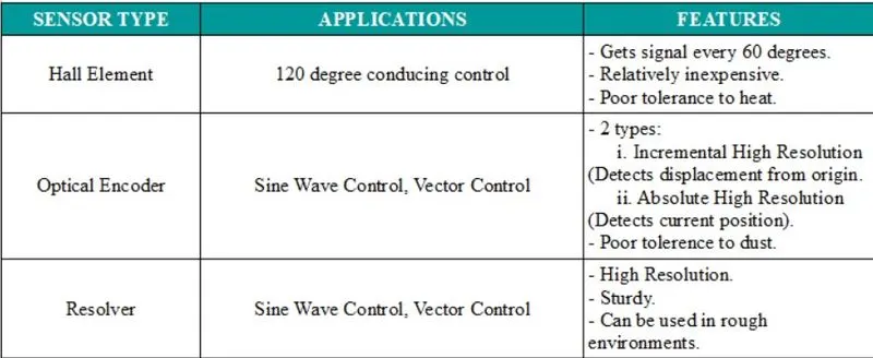
However, another crucial characteristic of these motors that we haven't discussed yet is their positioning sensors. Because the rotor (magnet) position must be coordinated with the BLDC motor control, these motors usually contain sensors to detect this position. When current is applied when the rotor location is uncertain, the rotor may turn in the incorrect direction. The introduction of sensors eliminates this issue.
Vector Control Maintains High Efficiency
Sinusoidal control, as we've seen, provides smooth rotation by using the 3-phase current to regulate the flux. Whereas 120-degree conducting control energizes just two of the three phases (U, V, and W) at a time, sinusoidal control is far more difficult since it must properly provide different amounts of current to all three phases.
Vector control, in which computations are employed to change the coordinate space, allows 3-phase AC data to be treated as 2-phase DC values, is one technique to reduce this difficulty. However, this method can only function if high-resolution positional data is available for use in the calculations. The use of high-precision sensors is one method of obtaining this information (optical encoders, resolvers, etc.). Estimating the location based on the amount of current entering each phase is another "sensor less" method. In any instance, converting the coordinate space enables direct control of torque-related electric current, resulting in extremely efficient operation with the minimal wasted current.
Vector control implementation necessitates extensive mathematical processing, including the ability to compute trigonometric functions quickly enough to change the coordinate space. The MCU used to drive these motors will almost always include an FPU (floating-point unit) and will need to be capable of delivering a significant amount of computing power.