Otto-Cycle using MATLAB
AIM:
To plot the PV – Diagram of Otto-cycle using MATLAB and calculate its thermal efficiency.
What is Otto-Cycle?
It’s a description of what happens to the mass of gas as it is subjected to changes of pressure, temperature, volume, and addition & removal of heat.
The mass of gas that is subjected to those changes is called a SYSTEM. The system in this case is defined to be the fluid (gas) within the cylinder.
It is derived from:
- TOP to BOTTOM –
A pair of Quasi-Parallel & Isentropic Compression (Frictionless Adiabatic Reversible)
- LEFT to RIGHT –
A pair of Isochoric Process (Constant Volume)
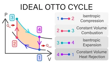
The Isentropic compression/expansion implies that there would be no efficiency (loss of mechanical energy) and there would be no transfer of heat into/out of the system during that period.
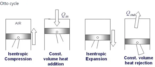
The four processes:
- ADIABATIC COMPRESSION (1 – 2, Stroke-1):
The air-fuel mixture is compressed isentropically inside the cylinder.
- CONSTANT VOLUME HEAT ADDITION (2 – 3, Stroke-2):
The combustion takes place inside the cylinder due to the spark from the spark-plug.
- ADIABATIC EXPANSION (3 – 4, Stroke-3):
Due to high temperature and high pressure inside the cylinder, gases expand isentropically.
- CONSTANT VOLUME HEAT REJECTION (4 – 1, Stroke-4):
Gases come out of the ejection valve from the cylinder and the cycle is completed.
DESCRIPTION:
We’re going to plot a PV – Diagram of an Otto-Cycle and find out its efficiency.
There are terminologies that are used such as BORE, STROKE, CONNECTING ROD LENGTH, COMPRESSION RATIO, SWEPT VOLUME, and CLEARANCE VOLUME.
BORE (bore)– It’s the diameter of the engine cylinder.
STROKE (stroke)– It’s the distance within the cylinder the piston travels.
CONNECTING ROD LENGTH (conR_L)– It is measured between the centers of the crankshaft journal bore and the piston pin bore. It’s measured in inches or millimeters.
COMPRESSION RATIO (C_R)– It’s defined as the ratio of the volume above the piston when it is at the Bottom-Dead-Centre (BDC) to the volume above the piston when it is at the Top-Dead-Centre (TDC). It indicates the extent to which the air-fuel mixture is compressed in the engine.
SWEPT VOLUME (V_Swept)– Volume swept by the engine piston during the first stroke. It's also the product of piston area and stroke.
CLEARANCE VOLUME (V_Clearance)– Volume between the cylinder head and the piston when the piston is at TDC. THE RATIO OF CLEARANCE VOLUME TO THE SWEPT VOLUME DETERMINES THE COMPRESSION RATIO OF THE ENGINE.
THETA – Crank angle
EFFICIENCY OF OTTO CYCLE(EFFICIENCY_OTTO) – Thermal efficiency of the Otto-cycle.
P1, P2, P3, P4 – Pressure (in Pa) at state-points – 1, 2, 3 & 4(respectively)
V1, V2, V3, V4 – Volume (in m3) at state-points – 1, 2, 3 & 4 (respectively)
T1, T2, T3, T4– Temperature (in K) at state-points – 1, 2, 3 & 4 (respectively)
EQUATIONS USED:
- V_Swept = π/4 x bore2 x stroke
- V_Clearance = V_Swept / (Compression Ratio – 1)
- P X Vγ = C (constant)
- P X V / T = C (constant)
- V/ V_Clearance = 1 + 0.5 x (C_R - 1)[R + 1 – cosθ - √(R2 – sin2θ)]
- A = Stroke/2 (where, A = Crank-pin radius)
- R = conR_L/A (where, R = Ratio of connecting rod length to the crank-pin radius)
- μth = 1 – 1 / rγ-1
PROCEDURE FOLLOWED IN PROGRAMMING:
Bore = 0.1m Connecting Rod length = 0.15m P1 = 101325 Pa T1 = 500 K
Stroke = 0.1m Compression Ratio = 12 T3 = 2300 K Gamma = 1.4
Using the above inputs,
Swept Volume = 7.85e-04, V1 = 8.56e-04,
Clearance Volume = 7.13e-05, V2 = 7.13e-05
At state-point-2, P X Vγ = C (constant), using this equation, P2 = P1 x (V1/V2) γ
which gives P2 = P1 x C_Rγ
=> P2 = 3.28e+06
Since, P1V1/T1 = P2V2/T2
=> T2 = P2 x V2 x T1 / P1 x V1
=> T2 = 1.35e+03
At state-point-3, Volume is constant and the Pressure changes, so the pressure is calculated using the IDEAL GAS LAW EQUATION, P2/T2 = P3/T3
=> P3 = P2 x T3 / T2
=> P3 = 5593140
At state-point-4, Volume remains constant, while the Temperature and the Pressure values changes. So V4 = V1
and P3V3γ = P4V4γ
=> P4 = P3 x (V3/V4) γ
=> P4 = 1.72e+05
P3V3/T3 = P4V4/T4
=> T4 = P4 x V4 x T3 / P3 x V3
=> T4 = 851.25
Now, the thermal efficiency of the Otto-cycle is
η = 1 – 1/C_R γ-1
which comes out to be η = 0.629893
A graph is plotted between Pressure & Volume using the plot() command, and to obtain the curve during the process of expansion and compression, formula used is
V/ V_Clearance = 1 + 0.5 x (C_R - 1)[R + 1 – cosθ - √(R2 – sin2θ)]
Program to execute the PV-Diagram and its efficiency-
clear all
close all
clc
%*******PROCESSES*********
% 1-2 => ISENTROPIC PROCESS
% 2-3 => CONSTANT VOLUME HEAT ADDITION
% 3-4 => ISENTROPIC EXPANSION
% 4-1 => CONSTANT VOLUME HEAT REJECTION
% Inputs for the system
% V1 = VOLUME AT STATE 1 (Total volume)
% T1 = TEMPERATURE (IN KELVIN) AT STATE 1 IN
% P1 = PRESSURE (IN ATM) AT STATE 1
% C_R = COMPRESSION RATIO
% V2 = VOLUME AT STATE 2 (Volume at topdead centre (TDC), clearance volume)
% P2 = PRESSURE AT STATE 2
% T2 = TEMPERATURE AT STATE 2
% T3 = TEMPERATURE AT STATE 3
% V3 = VOLUME AT STATE 3
% P3 = PRESSURE AT STATE 3
% ConR_L = LENGTH OF THE CONNECTING ROD
% C_R = V1/V2
% R = Ratio of connecting rod and the crank pin-radius
% A = Stroke/2. Crank Pin-Radius
% State variables
P1 = 101325 % Atmospheric pressure
T1 = 500 % Initial temperature
% Inputs
gamma = 1.4 % Adiabatic index
T3 = 2300 % Temperature at which combustion takes place
% Engine geometry parameters
bor = 0.1; % Bore
strk = 0.1; % Stroke
conR_L = 0.15; % Connecting_Rod_Length
C_R = 12; % Compression ratio
A = strk/2; % Crank Pin-Radius
R = conR_L/A; %
% Calculating the swept volume and clearance volume
V_Swept = (pi/4)* bor^2 * strk; % Volume swept by the engine piston
% during the first stroke
V_Clearance = V_Swept/(C_R -1); % VOLUME IN THE CYLINDER GAP.
V1 = V_Swept + V_Clearance;
V2 = V_Clearance;
% State variables at state-point-2
% P2V2^gamma = P1V1^gamma
P2 = P1 * C_R^gamma;
% For computing the Temperature at State-Point 2, we're using ideal gas law
% PV = nRT, so PV/T = constant => P1V1 / T1 = P2V2 / T2
T2 = (P2 * V2)*T1/(P1 * V1);
constant_C = P1 * V1^gamma
V_Compression = Piston_Kinematics(bor, strk, conR_L, C_R, 180, 0);
P_Compression = constant_C./V_Compression.^gamma;
% State variables at State-point 3.
V3 = V2; % Since V2 & V3 are on same line
V_Expansion = Piston_Kinematics(bor, strk, conR_L, C_R, 180, 0);
% Using the ideal gas law, P2V2 / T2 = P3V3 / T3
P3 = P2 * T3 / T2; % V2 & V3 get cancelled out as V2 = V3
% Here, the value of P3 > P2 as when the combustion
% process takes place, the pressure would
% substantially be highest.
% P2V2^gamma = constant_C
constant_C = P3 * V3^gamma;
P_Expansion = constant_C./V_Expansion.^gamma;
% State variables at State-point 4.
% Volume at StatePoint - 4 = Volume at StatePoint - 1
V4 = V1
% P3V3^gamma = P4V4^gamma
P4 = P3 * (V3/V4)^gamma;
figure (1)
hold on
grid on;
xlabel ('Volume (m^3)');
ylabel ('Pressure (Pa)');
plot (V1, P1, '*', 'color', 'r');
plot (V_Compression, P_Compression, 'color', 'g');
text (V_Compression(75), P_Compression(75), 'ISENTROPIC COMPRESSION', 'color', 'g');
plot (V2, P2, '*', 'color', 'r')
plot ([V2, V3], [P2, P3], 'color', 'r');
plot (V3, P3, '*', 'color', 'r')
plot (V_Expansion, P_Expansion, 'color', 'b');
text (V_Expansion(85), P_Expansion(85), 'ISENTROPIC EXPANSION', 'color', 'b');
plot (V4, P4, '*', 'color', 'r')
plot ([V4, V1], [P4, P1], 'color', 'r');
% Thermal Efficiency of the cycle
% Efficiency = Net Work/Heat(input)
effciency_Otto = 1 - 1/(C_R^(gamma-1))
fprintf ('The thermal efficiency of the Otto-Cycle is %f ', effciency_Otto);
Function program-
function [Volume_trace] = piston_Kinematics (bor, strk, conR_L, C_R, start_crank, end_crank)
A = strk/2; % Crank pin radius
R = conR_L/A;
V_Swept = pi/4 * bor^2 * strk; % Swept volume
V_Clearance = V_Swept/(C_R-1); % Clearance volume
theta = linspace (start_crank, end_crank, 100);
term1 = 0.5*(C_R-1);
term2 = R + 1 - cosd(theta);
term3 = (R^2 - sind(theta).^2).^0.5;
Volume_trace = (1 + term1 * (term2 - term3)).*V_Clearance;
end
OUTPUT:
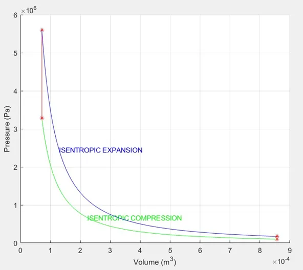
ERRORS: (Those errors which should be avoided or are done if care and attention are paid while plotting the graph and while doing the calculations.)
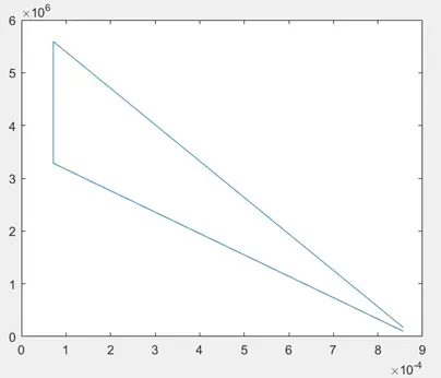
- Error – 1: While plotting the graph such errors are done while using the simple and single plot command
plot ([V1 V2 V3 V4], [P1 P2 P3 P4])
Here, we get a linear plot without any proper curve
- Error – 2: While using ^ operator
SOLUTION: Use .^ instead of only ^ operator as .^ will do an element-wise operation.
- Error – 3: Not using the required number of input arguments in the function.
SOLUTION: Using the required number of input arguments
CONCLUSION:
After analyzing the PV characteristic of the OTTO-CYCLE, we come to the conclusion that the efficiency of the engine can be improved by changing the values of bore and stroke.