Week-7 Challenge: DC Motor Control
PART1 A: Explain a MATLAB demo model named 'Speed control of DC motor using H bridge'
Explanation:This method is used to control the speed by varying the duty cycle with the help of a pulse generator and we can get the required speeds here.
The bipolar junction transistor(BJT) when used for power switching applications, operates as an IGBT. When it is conducting(BJT operating in the saturated region), a forward voltage vf is developed between collector and emitter(in the range of 1v). Therefore the IGBT block can be used to model the BJT device.
The IGBT block does not simulate the gate current controlling the BJT or IGBT. The switch is controlled by a Simulink signal (1/0). The DC motor uses the preset model(5HP 240V 1750RPM). It simulates the fan type load(where load torque is proportional to the square of speed). The armature means voltage can be varied from 0 to 240v when the duty cycle(specified in the pulse generator) is varied from 0 to100%.
The H bridge consists of four BJT/diode pairs. Two transistors are switched simultaneously Q1 and Q4 or Q2 and Q3. When Q1 and Q4 are fired, a positive voltage is applied to the motor, and diodes D2-D3 operate as free wheeling diodes when Q1 and Q4 are switched off. When Q2 and Q3 are fired, a negative signal is applied to the motor, and diodes D1-D4 operate as free wheeling diodes when Q2 and Q3 are switched off.
The figure shows the speed control of dc motor using H bridge
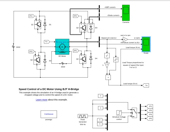
To get this mode into Simulink, write the model name in the help section and press enter, and a window with the model name will open and enter into the model then copy the command of the model and paste it into the MATLAB command window and press then model will open.
1B: Comment on the armature current shoot up from the scope results
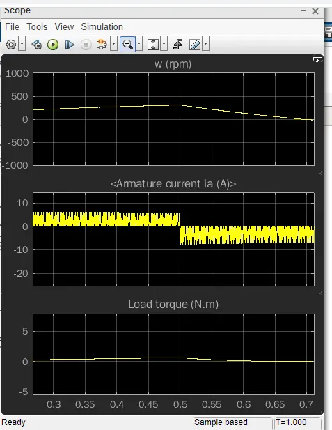
Run the model with the default value and the motor start in the positive direction with a duty cycle of 75%(mean DC voltage of 180v). At t=0.5s, the armature voltage is suddenly reversed and the motor runs in the reverse direction. After this duty cycle has changed to 50% and 40% and the resultant plots are also shown here.
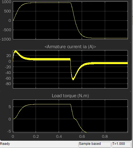
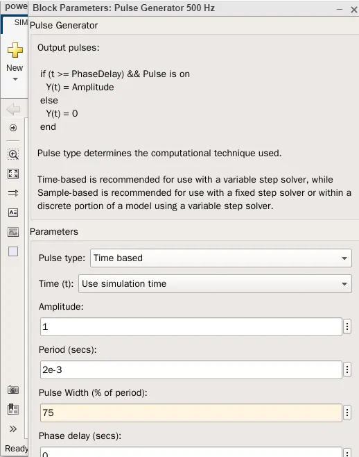
At duty cycle 75%
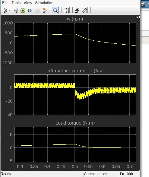
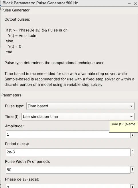
At duty cycle 50%
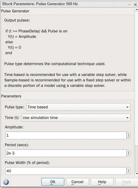
At duty cycle 40%
- If the duty cycle has 75%, the resultant plot shows the armature current has a higher value and sam as in the negative direction.
- In the above three plots, the armature current shoot up gets decreased and in the 3rd plot it almost flat shape and smooth current flows
- Reducing the duty cycle means reducing the applied voltage and the torque reduces proportional to it.
- NO two diodes in a line should not get triggered simultaneously otherwise a short circuit will happen.
- Armature current sta, is tha rts reducing if the duty cycle reduces.
- Because of switching the IGBTs for different duty cycles, heat will be generated. A heat sink can be used in the circuit to reduce the heat in the circuit.
1C: Comparison between Four-quadrant chopper dc drive(DC7) block and H-bridge model.
The four-quadrant chopper DC drive(DC7) BLOCK represents a four-quadrant, DC-supplied, chopper(or DC-DC PWM converter) drive for DC motors. This drive features closed-loop speed control with the four-quadrant operation. The speed control loop outputs the reference armature current of the machine. Using a PI current controller, the chopper duty cycle corresponding to the commanded armature is derived. This duty cycle is then compared with a sawtooth carrier signal to obtain the required PWM signals for the chopper.
The main advantage of this drive, compared with other DC drives, is that it can operate in all four quadrants(forward motoring, reverse regeneration, reverse motoring, and forward regeneration). In addition, due to the use of high switching frequency DC-DC converters, a lower armature current ripple (compared with thyristor-based DC drives) is obtained.
However, four switching devices are required, which increases the complexity of the drive system.
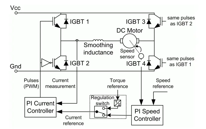
The Four-Quadrant Chopper DC Drive block uses these blocks from the Electric Drives/Fundamental Drive Blocks library
- speed controller(DC)
- Regulator switch
- Current controller(DC)
- Chopper
The below figure shows the model diagram of Four quadrant chopper dc drive in Simulink
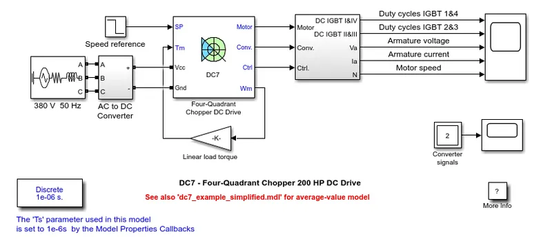
Comparison of four-quadrant chopper DC drive and H-bridge
- Both these drives have some advantages and disadvantages. H bridge DC drive is like a four-quadrant chopper DC drive can also have the capability of braking operation without using air resistance or friction or physical brakes to bring the motor to rest.
- Four quadrant DC choppers are mostly used in automobiles whereas BJT H-bridges are commonly used in robotics and electromechanical devices
- Four quadrant DC drive can perform both regenerative and dynamic braking but H-bridge can perform dynamic braking because of this four quadrant DC drives are used mostly in hybrid and electric vehicles
- In four quadrant DC choppers, the current signals are interrupted by one another to change the direction of rotation of the motor. This is done by the speed reference or duty cycle from which the speed values are converted to current signals which interrupt one another to change the rotation of the direction of the motor. However, in BJT H-bridges, the polarity of the current id is reversed(depending on the duty cycle) to change the direction of the rotation of the motor.
- The current signals in four-quadrant DC chopper drives are chopped which means they are not continuous they are discrete so takes less time for simulation but in BJT H-bridges, the current values are not chopped which means they are continuous and take more time for simulation
PART2: Develop a 2-quadrant chopper using Simulink and explain the working of the same with the relevant results
The two-quadrant chopper dc drive represents DC supplied chopper drive for DC motors. This drive features closed-loop speed control with the two-quadrant operation.
A dc-dc converter also known as a chopper is a static device that is used to obtain a variable DC voltage from a constant dc source.DC choppers are widely used in trolley cars, battery-operated vehicles, traction motor control, etc. They are also used as voltage regulators. Choppers are of two types namely step up and step down choppers. In step-down choppers, the output voltage will be less than the applied voltage, whereas, in step-up choppers, the output voltage will be more than the input voltage.
Choppers fed DC motor drives
DC motors are considered a SISO(single input and single output) system having torque/speed characteristics compatible with more mechanical loads. This makes a dc motor controllable over a wide range of speeds by proper adjustment of the terminal voltage.
The basic principle behind DC motor speed control is that the output speed of a DC motor can be varied by controlling the armature voltage for speed below and up to rated speed keeping the field voltage constant. The armature voltage can be controlled by controlling the duty cycle of the converter.
Two quadrant chopper model has developed in the Matlab and the model has shown below and the resultant plots too
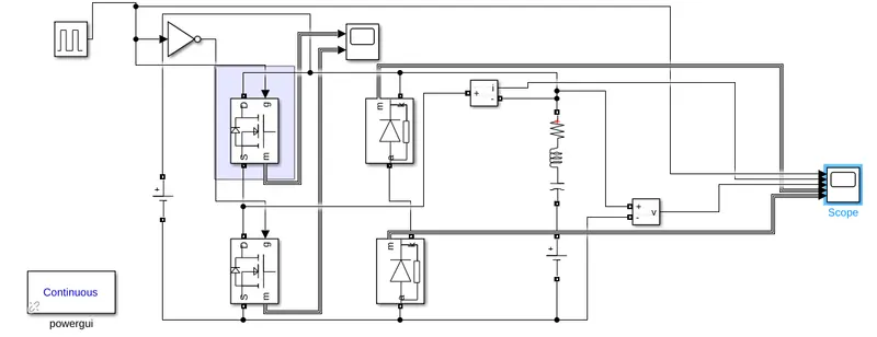
In this model, the duty cycle is considered as 50% and the dc input voltage its taken as24v and the dc voltage source at the load side is taken as 12v and in the RLC load R&C is considered as 0, and the inductor is taken as its default value and simulation has run for 30s.
Resultant plot:
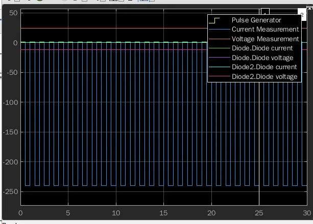
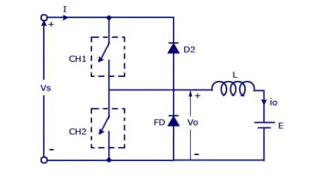
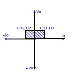
The resultant plot shows the output voltage will be positive but the current may be positive or negative. Two switches CH1and CH2 should not be turned ON simultaneously otherwise a short circuit will happen in the circuit. For regenerative braking and motoring, these types of chopper configurations are used.
We will always get a positive voltage when a freewheeling diode is used across the load. When mosfet1 is on the current flows from source to load. The inductor stores energy. When mosfet1 turns off the freewheeling diode starts conducting and the output voltage will be equal to the input voltage. The direction of the load current io will be reversed. The current io will be flowing towards the source. The load current will be flowing towards the source. The load current will be negative when the CH2 is ON. The current completes its path through diode D2.
PART4: Brief explanation of the operation of the BLDC motor.
BLDC Motor
A brushless dc electric motor is also known as an electronically commutated motor. It uses an electronic closed-loop controller to switch DC currents to the motor winding producing a magnetic field that effectively rotates in space and which the permanent magnet rotor follows. Primarily efficiency is the most important feature of this motor. Because the rotor is the sole bearer of the magnets and doesn't require any power i.e no connections, no commutators, no brushes. In places of these, the BLDC motor employs rotor encoders or a hall sensor along with controllers.
CONSTRUCTION
In this motor permanent magnets are attached to the rotor. the current-carrying conductors or armature windings are located on the rotor. They use electrical communication to convert electrical energy to mechanical energy. The main difference in design between brushed and brushless motors is the replacement of a mechanical regulator with an electric switch circuit. A BLCD motor is a type of synchronous motor in the sense that the magnetic field generated by the stator and rotor revolves at the same frequency.
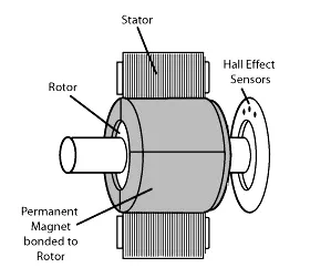
The Brushless motor does not have any current-carrying commutators. The field inside a brushless motor is switched through an amplifier which is triggered by the commutating device like an optical encoder.
WORKING
A Brushless dc motor works on the same principle as a brushed dc motor. The Lorentz force law state that whenever a current-carrying conductor is placed in a magnetic field experiences a mechanical force. As a consequence of the reaction force, the magnet will experience equal and opposite forces. In a BLDC motor, the current-carrying conductor is stationary and the permanent magnet is moving.
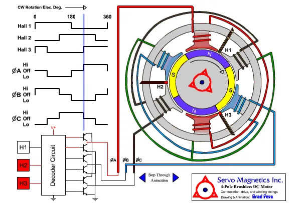
When a stator coil gets the supply from source, it becomes an electromagnet and starts producing a uniform magnetic field in the air gap. Though the source of supply is DC, switching makes to generate an AC voltage waveform with a trapezoidal shape. Due to the force of interaction between the electromagnetic stator and permanent magnetic rotor, the rotor continues to rotate.
With the switching of windings as low and high signals, corresponding windings energized as north and south poles. The permanent magnet rotor with north and south poles aligns with stator poles which causes the motor to rotate