Week -2
Simulink model of doorbell using solenoid block
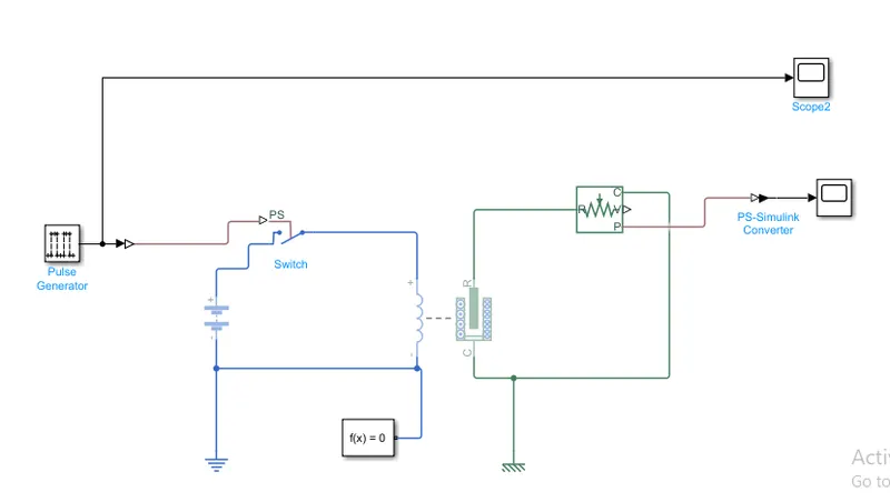
The above model shows the Simulink model of doorbell using solenoid
In this model pulse generator, switch, battery, solenoid, ideal translational motion sensor, scope, solver configuration, mechanical & electrical references,ps-Simulink & Simulink-ps converter blocks are used.
EXPLANATION OF MODEL
Initially, the pulses generated from the pulse generator make the switch ON when it gets the positive pulse. whenever the switch gets turn ON, the voltage from the battery appears across the solenoid and the solenoid acts like a magnet and it attracts the plunger then the doorbell makes the noise because of plunger movement. It will happen until the positive pules of the pulse generator become negative or the pulse generator becomes turn off. we can see the plunger movement in the graph by using a scope.
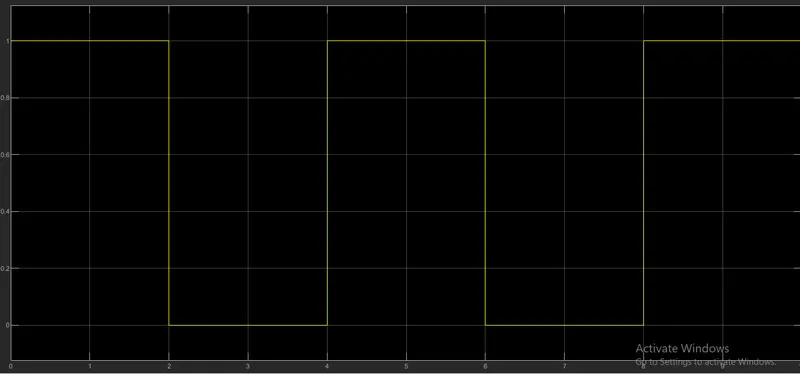
The above graph shows the input pules generated from the pulse generator.
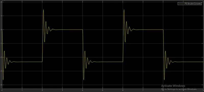
The above graph shows the output of this model and plunger movement according to the input pulses
2.The below model shows the thermistor used to sense the temperature and makes the fan turns on & off based on required conditions
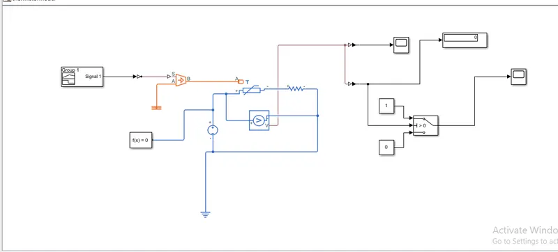
In the above model, I used different blocks to get the required model.
The resistor and the voltage sensor are connected across to each other. A repeating sequence waveform is connected in the model and the voltage sensor senses the different inputs of the repeating sequence. At every input, the outputs are recorded in the scope. The resistance of the resistor is set to any value but once the threshold voltage is identified the resistance should not change. The threshold temperature was given at 25 degrees Celcius and the corresponding voltage was found across the resistor through a display connected to the resistor. At this time, the repeating sequence was given only one value 298 kelvins. The output from the voltage was given to the switch in such a way that the switch gets ON or OFF based on the logical condition. The switch gets ON if the temperature is above 298k and the gets OFF if the temperature is below 298k.
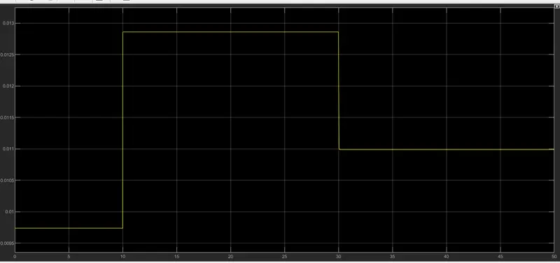
The above figure shows the input which is given to termistor circuit.
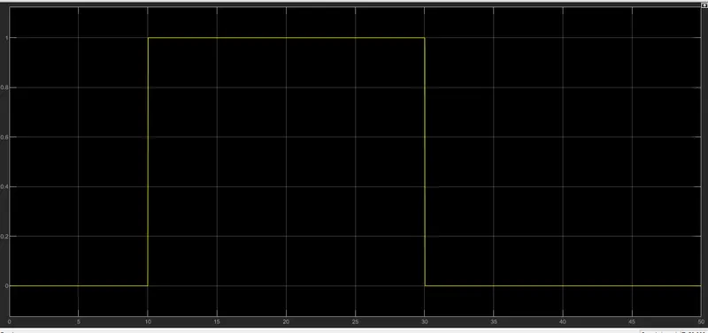
The above figure shows the output which is come at the scope connected to the switch. The fan gets ON/FF based on the condition given in the challenge. whenever the required voltage or the threshold voltage crosses, the switch automatically gets ON and becomes OFF when the threshold voltage becomes lower than the given voltage.