Week-6 Challenge: EV Drivetrain
PART1: Types of power converter circuits employed in electric and hybrid electric vehicles?
There are mainly four types of power circuit converters that are used in electric and hybrid electric vehicles.
A motor drive consists of a power converter and a controller. The power electronic converter handles the flow of power from the source to motor input terminals. The controller process the command input and the feedback information to generate the switching signals for power converter semiconductor devices.
AC - DC converter
This type of converter takes an ac input supply and converts it to supply. The power we are getting in our homes is 230v at a frequency of 50hz that we can use to power our electrical appliances. But in our home, some electrical appliances may take dc supply as input like chargers. For those appliances, we can use AC - DC converter to get the desired dc output. AC - DC converter will prevent the current from changing direction so that it can flow only unidirectional. A basic AC - DC converter circuit consists of a step-down transformer, thyristor, capacitor, and a low drop output voltage regulator(LDO).
A step-down transformer step-downs the voltage. An ac input waveform is a sinusoidal wave. It has both positive and negative cycles are present and these negative cycles are removed by using the thyristor this is called 'rectifying' and this part of the circuit is referred to as the rectifier circuit. Then this rectified output voltage waveform is smoothened by a capacitor. Finally, the LDO regulator will regulate the output voltage to our desired level.
DC - AC converters
This type of converter converts the DC input to AC one. Power supplied from a battery or a capacitor is in dc form and converted into ac by using DC - AC converter. For an instance, power supplied from the solar panels is dc and this power is stored in batteries which can be supplied to homes by the 'inverter circuit' which is nothing but DC - AC converter.
The dc supply is converted to ac by semiconductor switches which are basically IBGBTs, MOSFETs, etc. These switches are controlled by the controller to be either open or closed position to direct the flow of current in the circuit. The controller sends the signals to the switches to tell them open or close the, and even decides the frequency too. By doing this, the current changes to ac current and can feed to the load.
In the case of EVs AND HEVs, the battery pack will supply its power to the inverter. The inverter consists of a transformer and the semiconductor switches in the inverter change the input power dc to ac and will feed this ac power to the transformer. The transformer will send this power to the motor ac load which may be an ac traction motor.
DC-DC converter
This type of converter is similar to a transformer and it can change the voltage from one level to another level. This type of converter is called 'CHOPPER'.The purpose of using this type of converter is to power the particular components to their desired level and for the safety of the appliances and the user too. If a component is supplied with lower or higher voltages, it may not operate due to lack of voltage or it may get damaged, to avoid this a DC-DC converter is used.
It works by taking the dc supply and passing it through a switching element which converts the waveform to a square wave which is ac in nature. Then this ac is passed through a filter which will turn it back to a dc form but to our desired level for the load.
There are mainly 2 types of DC-DC converters isolated and non-isolated type. Non-isolated can be subdivided into the below types
- Buck converter - step down the voltage
- Boost converter - step up the voltage
- Buck/Boost - step-up/step-down the voltage operations but is mainly used to reverse polarity
The isolated can be subdivided into the below types
- Flyback converter - similar to buck-boost converter but it uses a transformer instead of an inductor to store energy
- Forward converter - This type uses a transformer to send energy between input and output in a single step.
AC - AC converter
This converter converts the ac waveform with a particular voltage and frequency to another ac waveform with a different voltage and frequency. This converter has many applications in our daily life i.e lamp dimming, and motor speed control. A cycloconverter is one type of AC-AC converter. This type of converter is also known as a frequency converter.
PART2:An electric vehicles power train with a 72v battery pack is shown in the diagram below. The duty cycle for acceleration operation is d1 and for braking operation is d2.
What is EV steady-state speed if the duty cycle is 70%?
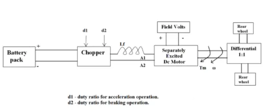
Motor and controller parameters:
Rated armature voltage = 72v
Rated armature current = 400A
Ra = 0.5ohms
Kϕ = 0.7 volt second
Chopper switching frequency = 400Hz
Vehicle speed torque characterstics is given as Tv = 24.7+(0.0051)w^2
AIM
Given duty cycle = 70% = 0.7
Voltage = Rated armature*Duty cycle
=72*0.7
=50.4v
Torque speed characterstics are calculated as
Tm = (Kϕ/Ra)*v + ((Kϕ)^2/Ra)*w
= (0.7/0.5)*50.4 + ((0.7)^2/0.5)*w
Tm = 70.56 - 0.98w_ _ _ equation(1)
Tv = 24.7+(0.0051)w^2_ _ _equation(2)
By equating above equations we can get
70.56 - 0.98w = 24.7+(0.0051)w^2
0.0051w^2 +0.98 -45.86 = 0
The above equation is quadratic equation and we can get the roots by the below equation,
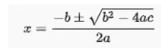
Substituting the equation values in above formula,
w = 0.98+((√(0.98)^2-4*0.0051*45.86)/2*0.0051) or w= 0.98-((√(0.98)^2-4*0.0051*45.86)/2*0.0051)
Speed should not be negative and we get the speed here is w = 38.92 rad/sec or
Steady-state of angular speed is = 38.92rad/sec.
PART3: Develop a mathematical model of dc motor for the below equation using simuliunk
w = V/Kϕ - Ra/Kϕ^2*T
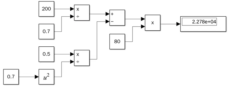
For creating the model for the above equation, we used different blocks and assumed some parameters for the model
V=200
Kϕ=0.7
Ra=0.5
T=80
The blocks which we are using here are CONSTANT blocks to assign voltage, torque, armature resistance,and switching frequency parameters and used some mathematical sign blocks to achieve the proper equation and display block to show off the final result.
PART4: Induction vs brushless dc motor by wally Rippel, tesla.Explain in brief the author's perspective
- In the blog on brushless and induction motors, the author is explaining the positive and negative points of both motors. He has explained the construction, working, and comparison of both motors.
- In brushless dc motors, Permanent magnets are used which produce the rotating magnetic field. when the current flows in the conductor which is placed in the magnetic field will experience the mechanical force and result in the rotation of the motor.
- Whereas in the case of an induction motor, the current is supplied to the induction motor which results in the generation of emf and this emf comes in contact with the rotor which is generally a squirrel cage type. This results in the current induced in the rotor. Unlike the dc motor, the rotor consists of conductor plates and is placed in a cage-like structure. This also has bars around them and current induced in it which results in rotation of rotor.
- A Brushless dc motor has produced less rotor heat as compared to the induction motor. Rotor cooling is easier and achieves peak point efficiency in a brushless dc motor and sometimes it can operate at a unity power factor. Whereas induction motor can operate at the maximum efficiency of 85%.
- The magnetic field strength in the brushless motor can be adjustable. when at low speed the maximum torque is required, the magnetic field should be maximum i.e inverter and motor current maintained at their lowest optimized efficiency. But in induction motor, there is no such adjustment.
- As the machine size increases magnetic losses increases proportionally in the brushless dc motor. But in induction motor, losses will be remains almost constant even if the machine size increases.
- The construction of a brushless dc motor is quite costly when compared to an induction motor due to the use of permanent magnets.
- In the author's point of view, Brushless dc motors will have the dominance in hybrid and plug-in hybrid vehicles and induction motors will have the dominance in pure EV vehicles.