Week - 4
1. Control logic of washing machine using state flow
A washing machine has different operating states like power supply, water filling, soaking, washing, etc. the control logic and state flow operate the washing machine automatically the washing machine uses centrifugal force by spinning 800-1600rpm to clean the dirt on the cloth with help of detergent and soap. this process is controlled by electric power using a motor, pump, heating, and valve. the dirty water drains through the outlet valve. It has main four processes and they are
SOAKING
It is used to dip clothes in detergent water to remove dirt from the clothes
WASHING
During the water cycle, a large agitator turns around moving your clothes through the water.
RINSING
The dirty soapy water is drained then the washing machine is refilled and clothes are rewashed in clean water.
DRYER
They work by pushing the warm dryer to wet washing to extract moisture and the heat exchanger condenses the moisture which is collected through the drain pipe. The air is reheated and the cycle repeats.
Control logic of washing machine
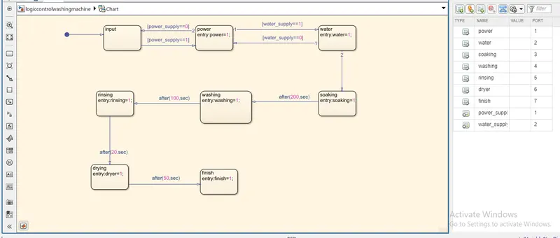
Input and output ports are given in the symbols pane and the condition which is given in the challenge are provided in the control logic diagram and the control logic diagram is drawn in the chart.
Model diagram of the washing machine
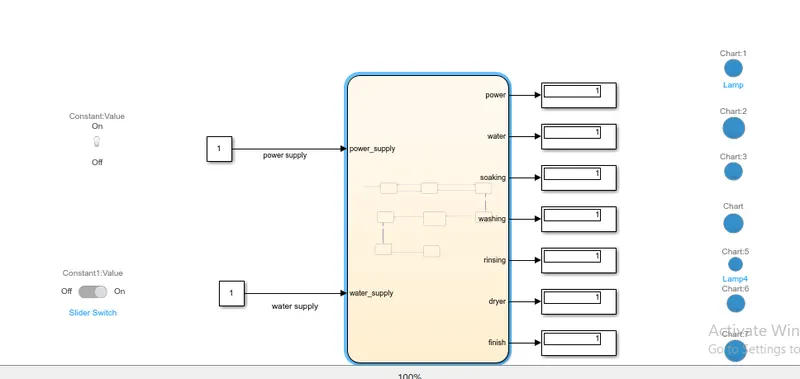
The input ports are connected to the power supply and water supply ports by using constant blocks and slider switches are connected to the input ports based on the condition given and the output ports are connected to the display units along with the lamp which is indicated on the condition given to that lamp.
2. Simulink chart for the gear shift indicator
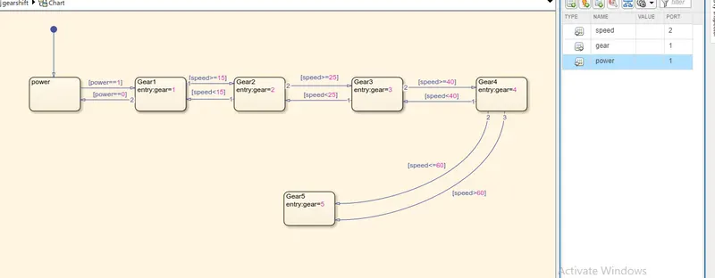
The below model shows the gear shift logic.
Here the logic diagram is drawn in the Simulink chart based on the conditions given in the chart and the below chart shows the gear shift logic
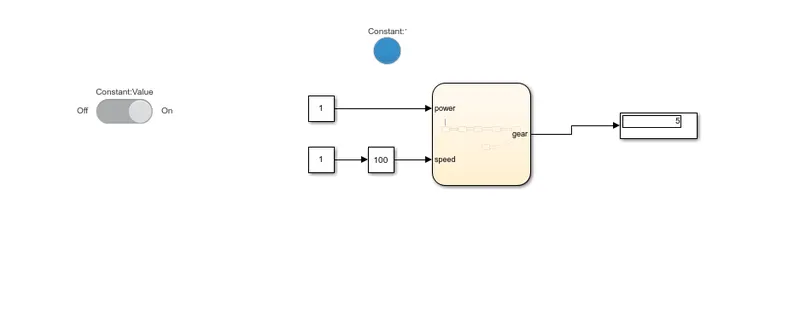
In the model diagram, a slider switch,slider gain, and a display unit is used
in the logic control g is used as the common parameter and is connected to the display block
Here the slider switch is used to control the power
Slider gain is used to raise the speed to the required value
Display unit is used to indicate the gear numbers
in order to run the simulation, simulation time kept infinite