Week-7 Challenge: DC Motor Control
1.
here they asked me to explain the MATLAB demo model named ‘Speed control of a DC motor using BJT H-bridge
so, i had opend the model in the simulink
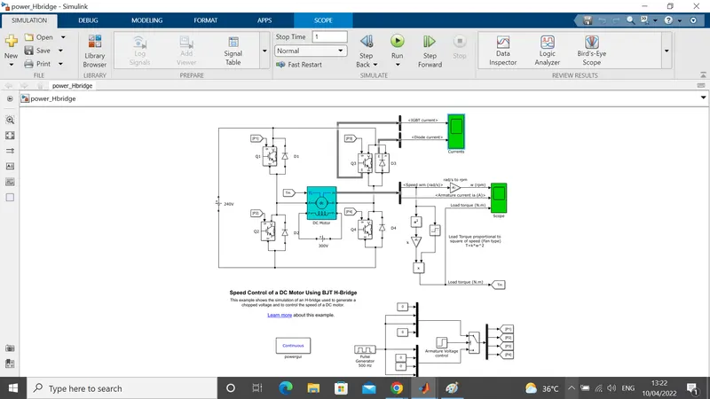
In the above Circuit the Input voltage is generated from the Pulse generator where the amount of supply and duty cycle is assigned in the Pulse generator
Pulse width = ON + OFF
Duty Cycle = ON/ON+OFF
D = PW/T
After pulse generator the connections are
Then the switch block is connected to Pulse generator through armature voltage control block.
The H-bridge consists of 4 BJT/Diode pairs (BJT Simulated by IGBT Models). Two transistors are switched simultaneously: Q1 and Q4 or Q2 and Q3
When Q1 and Q4 are fired, a positive voltage is applied to Motor and Diodes D2 – D3 operate as free-wheeling diodes, when Q1 and Q4 are switched off.
When Q2 and Q3 are fired, a negative voltage is applied to Motor and Diodes D1 – D4 operates as free-wheeling diode, when Q2 and Q3 are switched OFF.
A Switch block at bottom of circuit Splits the Power Supply into 4 parts namely they are [{p1} {p2} {p3} {p4}]. These inputs are in Goto form block.
That block is used to send signal to “From Block” that have the specified tag. If the tag visibility is “scoped”, then a Goto tag visibility block must be used to define the visibility of that particular tag. The block icon displays the selected tag name (local tag are enclosed in bracket “[]” and Scoped tag names are enclosed in braces” {}”).
Therefore these 4 types of Input are connected to transistor Q1, Q2, Q3, and Q4 through “From Block” ; An “From block” Receives the Signal from the “Goto Block” with the specified tag. The block icon displays the selected tag name (local tags are enclosed in [] brackets and Scoped tag names are enclosed in brace {} ,brackets)
SWITCHES:
Q1 and Q2 – Forward Motoring.
Q2 and Q3 – Reverse Motoring.
This formation is called an H-Bridge, An H-bridge is an arrangement of transistor that allows a circuit full control over a standard Electric DC Motor.
The DC Motor is connected to battery and the Mechanical Input of DC Motor is Initiated as torque. Load Torque Proportional to Square of Speed
1. (b)
here they asked me to Comment on the armature current shoot-up from the scope results
so after running the model the outputs are obtained and below i am attaching the images at different values of pulse width percentage
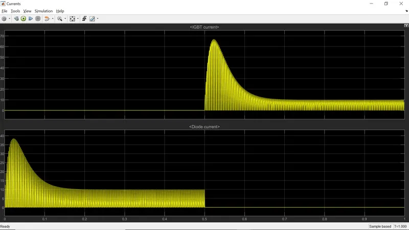
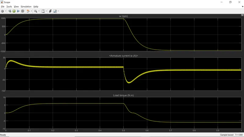
the above two scopes are taken when the pulse width percentage is at initial values
and now lets see if the pulse width percentage is increased by 80%
below i am attaching the scope images of both diode, igbt and armature current, speed scopes
due to some technical issue the images are not inserting, after contacting the technical team they suggested to insert those images as attachments. so, as per their advice below at the attachments section i am attaching the images (80% pulse change, IGBT and diode current scope & armature current, speed and torque scope)
so,here if we see in the both scopes before and after chaniging the pulse width percentage
In the Current output the amount of circuit acted is shown as the graphical representation during the period of duty cycle. The scope shows IGBT current and Diode current passed in the Quadrant Q3 and D3 (as initial current is in diode to start the circuit is in D3 diode).
Where Q3 represent as IGBT current and D3 is represented as Diode current in scope.
The Graph shows that when the Switch Q3 is OFF on the Starting Stage of Current flow and Diode current is on that stage. During the 0.5 sec of time D3 switch is ON that are given according to Pulse generator (step time in armature voltage control of 0.5)and after the time period of 0.5 sec D3 switch is OFF and IGBT current is acted after 0.5 sec and Q3 switch remains ON
The Speed and Armature current is obtained by the DC Motor and Load Torque is Calculated by load torque proportional to square of speed
In Starting point, there is a sudden Shootup is acted.
In this Scope shows that speed is increased in certain period of Time and at that time armature current is positive whereas Load Torque also moves forward.
After the time period of 0.5 sec which is given in Pulse generator (step time), sudden shoot-up is acted and speed gets decreased in that time armature current is in negative terminal whereas Torque act as reverse action.
Here the sudden shoot up is acted while Armature current is processed at a positive and negative terminal
1. (c)
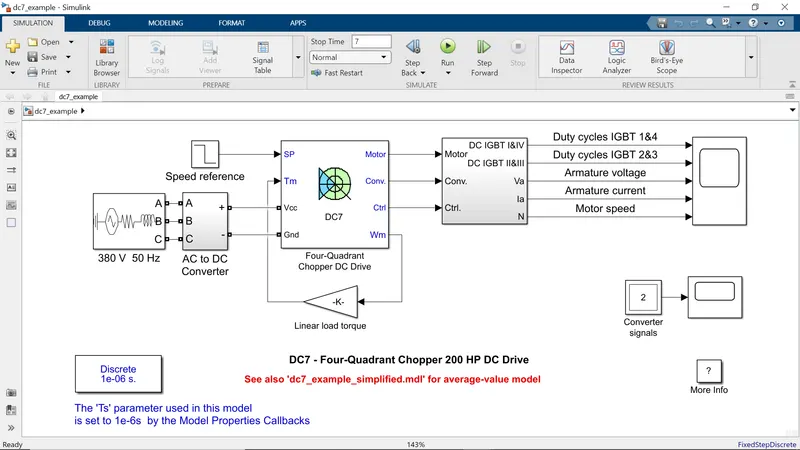
as they asked me to refer The Four-Quadrant Chopper DC Drive (DC7) block i had opened the model and studied it before getting into the model, i want to explain about a four-quadrent chopper
Four Quadrant Chopper or Class-E Chopper
A four quadrant chopper is a chopper which can operated in all the four quadrants. The power can flow either from source to load or load to source in this chopper. In first quadrant, a Class-E chopper acts as a Step-down chopper whereas in second quadrant it behaves as a Step-up chopper. This type of chopper is also known as Class-E or Type-E chopper. This article describes the working principle and operation of Class-E chopper with the help of circuit diagram
Working Principle / Operation of Class-E Chopper:
The circuit of a four quadrant chopper or class-E chopper basically consists of four semiconductor switches CH1 to CH4 and four diodes D1 to D4. The four diodes are connected in anti-parallel. The circuit diagram of this type of chopper is shown below.
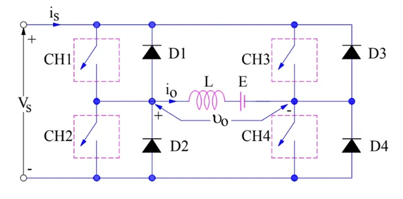
The choppers are numbered CH1 to CH4. For first quadrant operation CH1 is made ON, for second quadrant operation CH2 is made ON and so on. To better understand the working of four quadrant chopper, we will discuss its operation separately for each quadrant.
First Quadrant Operation:
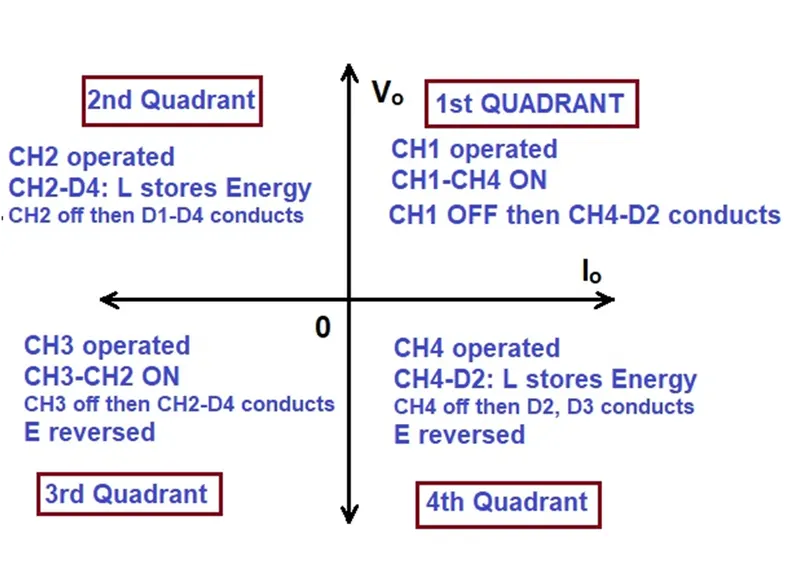
For first quadrant operation, CH4 is kept ON, CH3 is kept OFF and CH1 is operated. When both CH1 & CH4 are ON simultaneously, the load gets directly connected to the source and hence the output voltage becomes equal to the source voltage. This essentially means that vo = vs. It may be noted that the load current flows from source to load as shown by the direction of io.
When CH1 is switched OFF, the load current free wheels through CH4 and D2. During this period, the load voltage and current remains positive.
Thus, both the output voltage vs and load current io are positive and hence, the operation of chopper is in first quadrant. It may be noted that, Class-E chopper operates as a step-down chopper in this case.
Second Quadrant Operation:
To obtain second quadrant operation, CH2 is operated while keeping the CH1, CH3 & CH4 OFF. When CH2 is ON, the DC source in the load drives current through CH2, D4, E and L. Inductor L stores energy during the On period of CH2.
When CH2 is turned OFF, current is fed back to the source through D1, D4. It should be noted at this point that (E+Ldi/dt) is more than the source voltage Vs. As load voltage Vo is positive and Io is negative, it is second quadrant operation of chopper. Since, the current is fed back to the source, this simply means that load is transferring power to the source. Kindly read Step-up chopper for detailed analysis and better understanding.
For second quadrant operation, load must contain emf E as shown in the circuit diagram. In second quadrant, configuration operates as a step-up chopper.
Third Quadrant Operation:
To obtain third quadrant operation, both the load voltage and load current should be negative. The current and voltage are assumed positive if their direction matches with what shown in the circuit diagram. If the direction is opposite to what shown in the circuit diagram, it is considered negative. One important thing to notice is that the polarity of emf E in load must be reversed to have third quadrant operation. Circuit diagram of Class-E chopper for third quadrant operation is shown below.
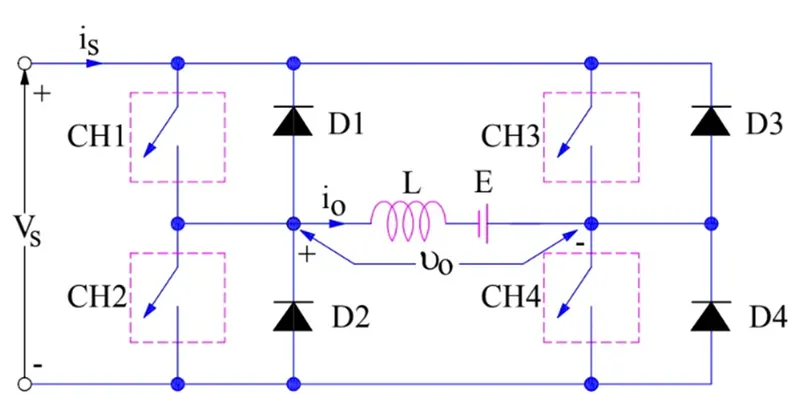
For third quadrant operation, CH1 is kept off, CH2 is kept ON and CH3 is operated. When CH3 is ON, load gets connected to source and hence load voltage is equal to source voltage. But carefully observe that the polarity of load voltage vo is opposite to what shown in the circuit diagram. Hence, vo is assumed negative. Let us now see what is the status of load current io. It may be seen that io is flowing in the direction opposite to shown in the circuit diagram and hence negative.
Now, when CH3 is turned OFF, the negative load current free wheels through the CH2 and D4. In this manner, vo and io both are negative. Hence, the chopper operates in third quadrant.
Fourth Quadrant Operation:
To obtain fourth quadrant operation, CH4 is operated while keeping CH1, CH2 and CH3 OFF. The polarity of load emf E needs to be reversed in this case too like third quadrant operation.
When CH4 is turned ON, positive current flows through CH4, D2, L and E. Inductance L stores energy during the time CH4 is ON. When CH4 is made OFF, current is fed back to the source through diodes D2, D3. Here load voltage is negative but the load current is always positive. This leads to chopper operation in fourth quadrant. Here, power is fed back to the source from load and chopper acts as a step-up chopper.
The operation of a four quadrant chopper or Class-E chopper is summarized in the figure below
now let us get into the model
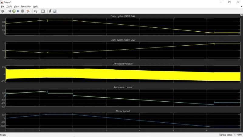
after running the model the output obtained in the scope is observed and attaching the image of the scope below
Comparison of Four-Quadrant chopper DC7 block vs. H-bridge model:
- Four-Quadrant Chopper can operates in all four modes (Forward Motoring, Forward Braking, Reverse Motoring and Reverse Braking), but H-bridge can operate only in two modes (Forward and Reverse).
- In Four-Quadrant Chopper Regenerative Braking is possible, but H-bridge Regenerative Braking is not possible.
- In Four-Quadrant Chopper Two PI regulator (Speed Regulator and Current Regulator) is used to obtain electromagnetic torque needed to reach the desired speed and control the armature current and stabilize the system, but in H-bridge model PI regulator is not used.
- H-bridge is an electronic circuit that switches the polarity of voltage applied to the load and Four-quadrant Chopper is electronic switch that is used to interrupt one signal under the control of another.
- H-bridge circuit is often used in Robotics and other applications to allow dc motor to run forward and backward. Four- Quadrant Chopper circuit is used to refer numerous type of electronic switching devices and circuits used in power control and signal applications
- Four-Quadrant Chopper model gives better efficiency and high energy(power) storage than H-bridge model
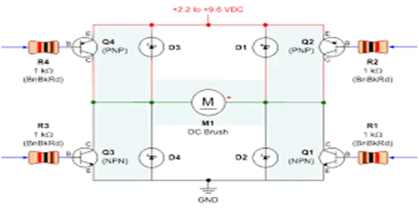
* Switch 1 and 4 are Closed, when motor needs to operate in “Forward direction”.
* Switch 2 and 3 are Closed, when motor needs to operate in “Reverse direction “.These switches are control by Signals from power Electronic device setup at particular time duration.
* Power BJT H-bridge is a 3 terminal device with a large current and power handling capacity and offers high voltage resistance in OFF state. The construction of power BJT is slightly different than normal logic transistor. It as extra lightly doped region (n-) at Emitter and Collector to handle high voltage at entry and is called as Collector drift region
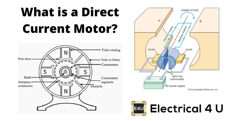
* A DC motor is any of a class of rotary electrical motors that convert DC current into Mechanical energy. The most common type relay on the force produced by Magnetic field. Nearly all DC motor have some internal mechanism, either electromechanically or electronic, to periodically change the direction of current in part of Motor.
* DC motors were the 1st form of motor widely used, as they could be powered from existing direct-current lighting power distribution systems.
* A DC motor’s Speed can be controlled over wide range, using either a variable supply voltage or by changing the strength of current in its Field winding.
2.
TWO - QUADRENT CHOPPER :
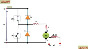
The Two-Quadrant Chopper block represents a two-quadrant controlled chopper for converting a fixed DC input to a variable DC output. The block contains two switching devices. Options for the type of switching devices are: GTO — Gate turn-off thyristor
-
deal semiconductor switch — For information about the I-V characteristic of the device, see Ideal Semiconductor Switch.
-
IGBT — Insulated-gate bipolar transistor. For information about the I-V characteristic of the device, see IGBT (Ideal, Switching).
-
MOSFET — N-channel metal-oxide-semiconductor field-effect transistor. For information about the I-V characteristic of the device, see MOSFET (Ideal, Switching).
-
Thyristor — For information about the I-V characteristic of the device, see Thyristor (Piecewise Linear).
-
Averaged Switch — Semiconductor switch with an anti-parallel diode. The control signal port, G, accepts values in the
[0,1]interval. When the value at port G is equal to0or1, the averaged switch is either fully opened or fully closed, and it behaves similarly to the Ideal Semiconductor Switch block with an anti-parallel diode. When the value at port G is between0and1, the averaged switch is partly opened. You can then average the PWM signal over a specified period. This allows for undersampling of the model or using modulation waveforms instead of PWM signals.
so, as we observe the two quadrent will either work in 1&2 quadrents or 1&4 quadrents
now lets get into the model in the simulation
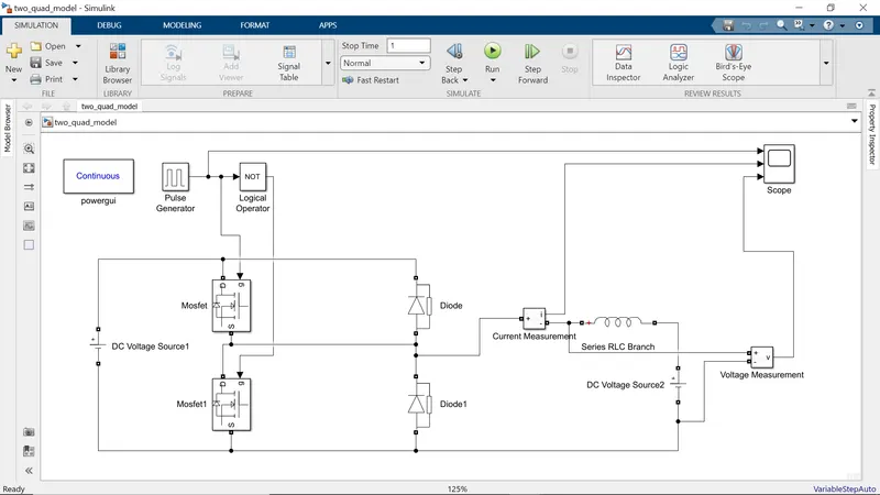
after connecting the all blocks and giving the desired parameters at first i had kept the initial value of pulse width at 50%
and then takin as run time for one second i have run the simulation and observed the output
and then after i changed the pulse width to 75% and keeping the run time as one second again irun the simulation and observed the output
due to some technical issue the images are not inserting, after contacting the technical team they suggested to insert those images as attachments. so, as per their advice below at the attachments section i am attaching the images (50% pulse width, scope of 50% pulse width & 75% pulse width, scope of 75% pulse width)
below i am attaching the model file of the simulink also. please go through it.
here the voltmeter is connected between the inductor load to measure the voltage between the load
the ammeter is connected in between the MOSFET and diode legs to observe the flow of current
if we see the both scopes in 50% & 75% the current and voltage values are higher in 75% compare than the 50% as we change the pulse width percentage in the pulse generator block.
3.
BLDC motor :
BLDC motor works on the principle similar to that of a Brushed DC motor. The Lorentz force law which states that whenever a current carrying conductor placed in a magnetic field it experiences a force. As a consequence of reaction force, the magnet will experience an equal and opposite force
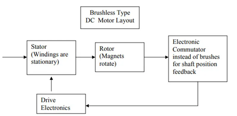
Primary efficiency is a most important feature for BLDC motors. Because the rotor is the sole bearer of the magnets and it doesn't require any power. I.e. no connections, no commutator and no brushes. In place of these, the motor employs control circuitry. To detect where the rotor is at certain times, BLDC motors employ along with controllers, rotary encoders or a Hall sensor.
Construction of Brushless DC motor
In this motor, the permanent magnets attach to the rotor. The current-carrying conductors or armature windings are located on the stator. They use electrical commutation to convert electrical energy into mechanical energy.
The main design difference between a brushed and brushless motors is the replacement of mechanical commutator with an electric switch circuit. A BLDC Motor is a type of synchronous motor in the sense that the magnetic field generated by the stator and the rotor revolve at the same frequency.
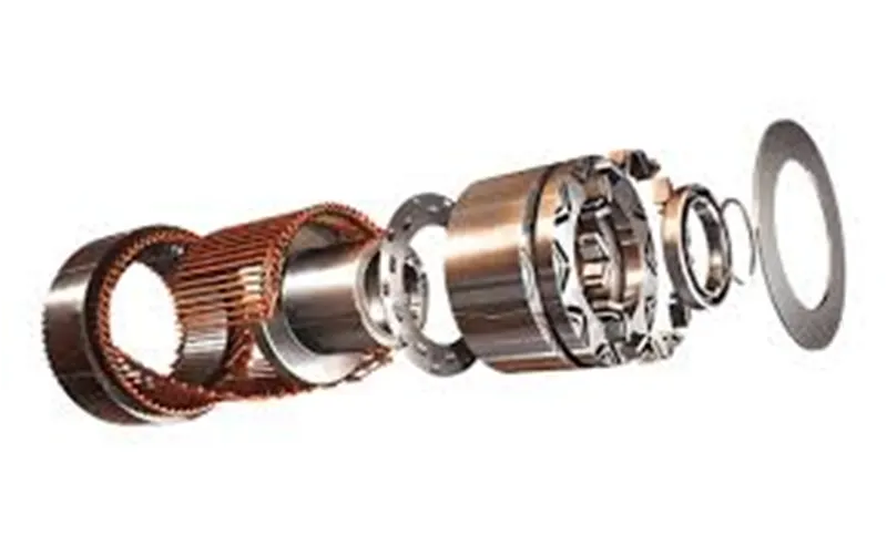
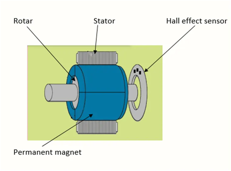
Brushless motor does not have any current carrying commutators. The field inside a brushless motor is switched through an amplifier which is triggered by the commutating device like an optical encoder.
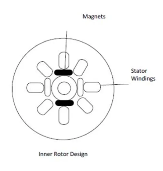
The layout of a DC brushless motor can vary depending on whether it is in “Out runner” style or “Inrunner” style.
- Outrunner –The field magnet is a drum rotor which rotates around the stator. This style is preferred for applications that require high torque and where high rpm isn’t a requirement.
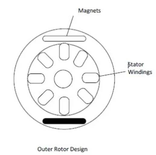
- In runner– The stator is a fixed drum in which the field magnet rotates. This motor is known for producing less torque than the out runner style, but is capable of spinning at very high rpm.
Working Principle of Brushless DC motor
BLDC motor works on the principle similar to that of a Brushed DC motor. The Lorentz force law which states that whenever a current carrying conductor placed in a magnetic field it experiences a force. As a consequence of reaction force, the magnet will experience an equal and opposite force. In the BLDC motor, the current carrying conductor is stationary and the permanent magnet is moving.
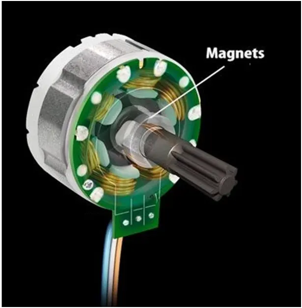
When the stator coils get a supply from source, it becomes electromagnet and starts producing the uniform field in the air gap. Though the source of supply is DC, switching makes to generate an AC voltage waveform with trapezoidal shape. Due to the force of interaction between electromagnet stator and permanent magnet rotor, the rotor continues to rotate.
With the switching of windings as High and Low signals, corresponding winding energized as North and South poles. The permanent magnet rotor with North and South poles align with stator poles which causes the motor to rotate.
Advantages of Brushless DC motor
- Less overall maintenance due to absence of brushes
- Reduced size with far superior thermal characteristics
- Higher speed range and lower electric noise generation.
- It has no mechanical commutator and associated problems
- High efficiency and high output power to size ratio due to the use of permanent magnet rotor
- High speed of operation even in loaded and unloaded conditions due to the absence of brushes that limits the speed
- Smaller motor geometry and lighter in weight than both brushed type DC and induction AC motors.
- Long life as no inspection and maintenance is required for commutator system
- Higher dynamic response due to low inertia and carrying windings in the stator
- Less electromagnetic interference
- Low noise due to absence of brushes
Limitations of Brushless DC motor
- These motors are costly
- Electronic controller required control this motor is expensive
- Requires complex drive circuitry
- Need of additional sensors
Applications of Brushless DC motor
Brushless DC motors (BLDC) use for a wide variety of application requirements such as varying loads, constant loads and positioning applications in the fields of industrial control, automotive, aviation, automation systems, health care equipments etc.
- Computer hard drives and DVD/CD players
- Electric vehicles, hybrid vehicles, and electric bicycles
- Industrial robots, CNC machine tools, and simple belt driven systems
- Washing machines, compressors and dryers
- Fans, pumps and blowers
kindly please go through the below attachments of the obtained scope images and model files
Thank you
B. V. N. SANDEEP