Week -2
1.
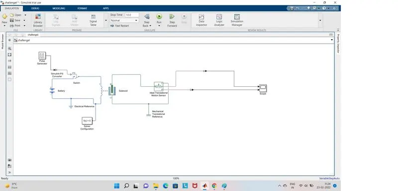
Here they asked me to build a door bell with a following condition i.e. the switch should closed for every 2sec and then released. so, here i used a pulse generator to generate a signal as per the given condition. and here as i am using a switch and the signal is directly given to the switch we are using 'simulink-ps converter' (which converts simulink signal to physical signal)
*here the signal generator generates a signal as per our given condition, and the switch is operated according to that signal input.
*when the switch is closed the circuit is closed and the power is flowed to the solenoid electrical part and when the power flows in the solenoid the electromagnetic force is produced and there will be a movement in a solenoid part (RC).
*here i am using ideal transational motion sensor in the place of bell, and the R&C terminals of a solenoid is connected to the R&C terminals of a ideal transational motion sensor.
*and P&C terminals of a ideal transational motion sensor is connected to the scope
*here i had used a solver configuration block because physical network represented by a connected Simscap block diagram requires solver settings information for simulation
*i also connected the electrical reference and Mechanical Translational Reference to the respective circuits to avoid any faults in the circuit
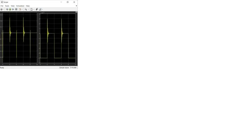
So, here i am running this for 10sec, when ever the switch is closed the power is fed to the solenoid and due to the electromegnatic force is produced there will be a movement in R&C terminals and according to that only the ideal transational motion sensor is operated
and the scope results are also attached below
2.
Here they asked me to build a temparature sensor by using thermistor. and also given the conditions where the fan should be turned on and off
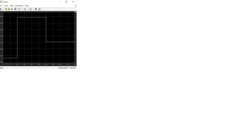
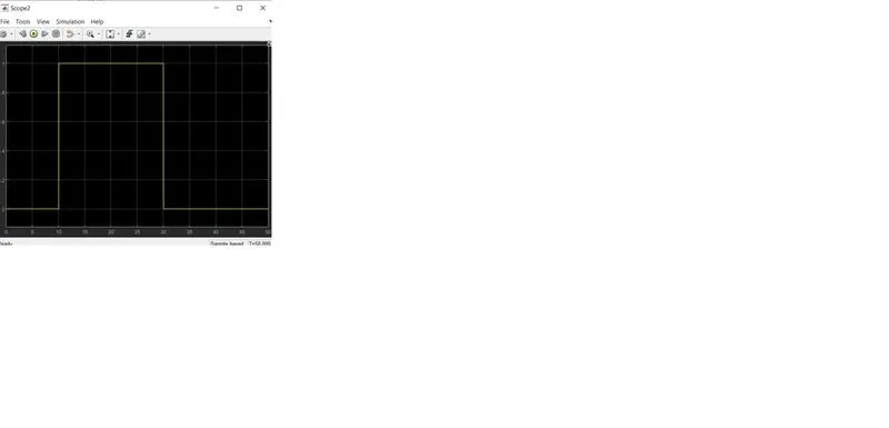
* here the given condition are the temparature should be 20 °C from 0 to 10 seconds, 27 °C from 10 to 30 seconds, 23 °C from 30 to 50 seconds
* and the given fan conditions are the fan should be ON if the temperature above 25 °C, OFF otherwise
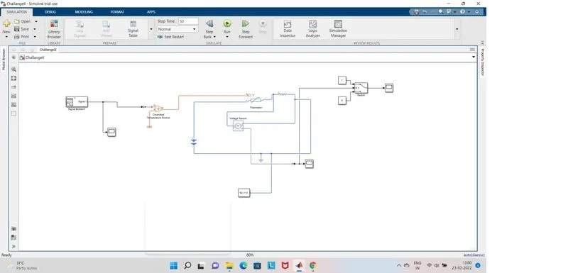
* so, here i took controlled temparature source as there should be some temparature input to the thermistor
* and the temparature in the temparature source is controlled by a signal builder and that signal builder is set as per our given temparature conditions
* so as per the condition given in the signal builder the temparature is produced in the temparature source
* here i converted the given temparature into kelvin and given input in a signal builder
* so here the voltage source is connected to the thermistor and a resistor is connected in series with thermistor, as the temparature vary the voltage across the the thermistor and the resistor also changed
* the volatage sensor is connected in parallel with the resistor to observe the voltage across the resistor
* here the switch is taken and the theshold value of that switch is defined and the second port of the switch is connected to the output of the voltage source and for the first port of the switch, the constant is connected with a value of 1 and for the third port of the switch, constant is connected with a value of 0
* here the constant value 1 means it indicates that the switch is in on position and the constant value 0 means it indicates the switch is in off position
* so, here according to our condition the treshold value is determined and depending on that value the switch is operated or on and off
* so depending on that the fan can be connected and it will be at on condition when the temparature is above 25 °C and at be off position at remaining condition
* here i had used a solver configuration block because physical network represented by a connected Simscap block diagram requires solver settings information for simulation
* and also connected the reference block to the circuit
* here i run simulation for 50sec because the given time in the above condition is of 50sec and the results are observed
* the images of the block diagram and scope results are plotted below
and the simulation models are also attached below
THANK YOU