Week-6 Challenge: EV Drivetrain
1.
All-electric vehicles (EVs), also referred to as battery electric vehicles, use a battery pack to store the electrical energy that powers the motor. EV batteries are charged by plugging the vehicle in to an electric power source.
So, for this charging and usage there will be a need of power converting at different kind of stages. So, for that purpose we use different kind of power converters and different kind of converting circuits.
So, now let’s see different kind of converts used :
- AC-AC converters
- DC-DC converters
- AC-DC converters
- DC-AC converters
- BUCK and BOOST converters
- BRIDGE converters… and more
AC – AC CONVERTER
AC to AC converters is used for converting the AC waveforms with one particular frequency and magnitude to AC waveform with another frequency at another magnitude. This conversion is mainly required in case of speed controlling of machines, for low frequency and variable voltage magnitude applications as well.
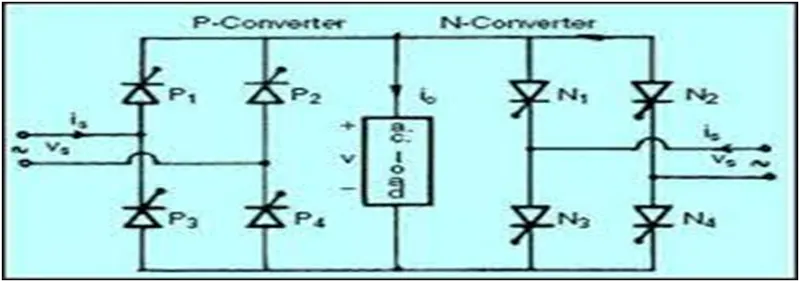
DC –DC CONVERTER
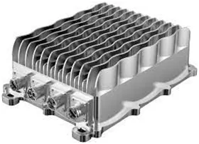
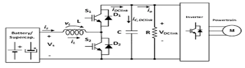
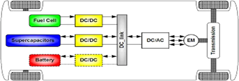
DC-DC converters convert HV to 48V, HV to 12V, and 48V to 12V in the various configurations of electric vehicles. The key design requirements for DC-DC converters are low losses, high efficiency, low volume and light weight. There are much architecture requiring different kinds of semiconductor devices.
Electric vehicles (EV) use two different power systems; a high-voltage battery (200 to 450 VDC) for traction and a low-voltage (12 V) one for supplying all the electric appliances
AC – DC CONVERTER
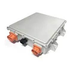
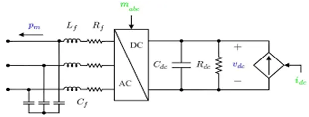
An AC to DC converter circuit does exactly as its name implies: it takes a harmonic AC input and converts it to a DC output. These circuits are simply from a high level and when operating at low power on a breadboard, but a real AC to DC converter circuit is more complex than just a transformer and rectifier circuit.
EVs release no tail pipe air pollutants at the place where they are converter. They also typically generate less sound pollution than an indoor combustion engine vehicle, whether at rest or in motion. Adaptation of EVs would have a big net environmental benefit. In modern era almost every household electronics works on DC but we got AC from power generation via transmission lines because AC can be transmitted more efficiently than DC in lower cost.AC to DC converter uses rectifier to turn on AC input into DC output regulators to adjust the voltage level and reservoir capacitor to smooth the pulsating DC
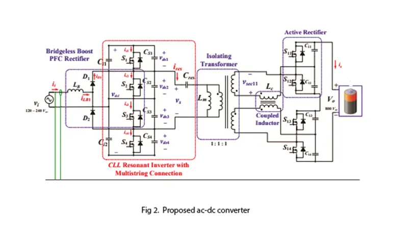
DC – AC CONVERTER
DC-to-AC Converters are one of the most important elements in power electronics. This is because there are a lot of real-life applications that are based on these conversions. The electrical circuits that transform Direct current (DC) input into Alternating current (AC) output are known as DC-to-AC Converters or Inverters. They are used in power electronic applications where the power input pure 12V, 24V, 48V DC voltage that requires power conversion for an AC output with a certain frequency.
]The DC-to-AC Converters are used to charge the batteries in the vehicles. These circuits are mainly used for driving low-power AC motors and are used in a solar power system. The DC to AC converters can be used in dc transmission lines for transmitting power to loads
BRIDGE CONVERTERS :
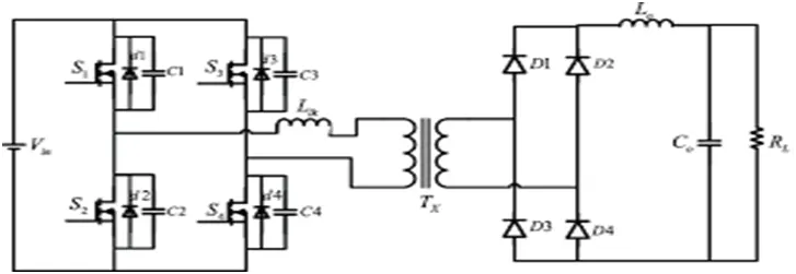
A Bridge Converter is a DC to DC converter topology (configuration) employing four active switching components in a bridge configuration across a power transformer. This has lower losses than a bridge rectifier.
A full bridge converter is one of the commonly used configurations that offer isolation in addition to stepping up or down the input voltage. Other functions may include reversing the polarity and providing multiple output voltages simultaneously.
A full bridge single phase inverter is a switching device that generates a square wave AC output voltage on the application of DC input by adjusting the switch turning ON and OFF based on the appropriate switching sequence, where the output voltage generated is of the form +Vdc, -Vdc, Or 0.
and many more power converters are used but i only defined the major converters used.
2.
here,
let’s see the given data
Motor and Controller Parameters:
Rated Armature voltage= 72 V
Rated armature current (Ia) = 400 A
Armature resistance (Ra) = 0.5Ω,
Motor constant (KΦ) = 0.7 Volt second
Chopper Switching frequency= 400 Hz
Asked to find EV steady state speed if duty cycle is 70%
Here the duty cycle is given in percentage so, 70/100 = 0.7
So, the actual voltage is given by
= 0.7*72
= 50.4 v
So, as we know the torque equation of the motor is
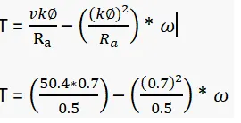
T = 70.56 – 0.98 *
Now lets see the given equation from the given question

Now lets solve the above two equations
24.7 + (0.0051) ω2 = 70.56 – 0.98 * ω
0.0051 ω2 + 0.98 ω - 45.86 = 0
As it is a quadratic equation we get values as
ω = 38.915 rad/sec and ω = -231.07 rad/sec
so, we should consider always the positive value
so, the EV steady state speed if the duty cycle is 70% is 38.915 rad/sec
so, the speed will be the 371.610877 RPM
3.
here they asked me to buid a model for the following equation ω= V/Kϕ - Ra/Kϕ^2 .T
so i had built according they asked me, below i am attaching the picture of my model
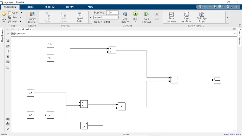
i had run this for 10 sec, after running the module the output is obtained and i amattaching the image of my obtained scope in below
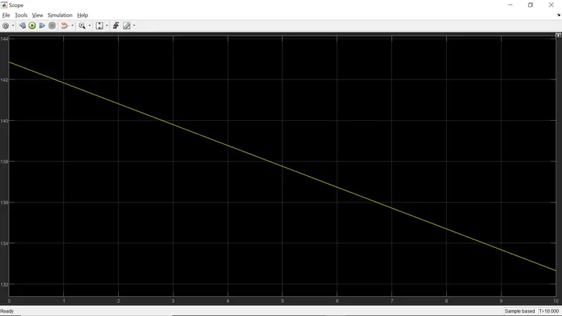
as we know that the speed is inversely proportional to torque
and below i am also attaching the simulation file of the model.
4.
here they asked me to Refer to the blog on topic Induction Versus DC brushless motors by Wally Rippel, Tesla
so after going through is documentation I came to know that he is a power electronics engineer in the tesla motors and he want to discuss about the topic of induction vs DC brushless motors
* In the beginning, the he described about the (IC) Internal Combustion Engines in the world of the automobile industry and also discusses different types of engines.
* He explains that all engines were similar and it was up to the user to select according to their need. He also discussed about induction motor and brushless DC motors and presents his view that these two technologies will be widely used in the future
* he also mentioned about the sizes of an gas based vehicles and also mentioned the same properties about the electric vehicles.
* Then he also explained the difference between the DC motor and induction motor and their uses in EV designing, and also discussed about their advantages and disadvantages
* And he said about DC brushless motor and that they contains permanent magnets which generates DC magnetic field. And also mentioned about the current controlled device known as inverter. And he also mentioned that without this device brushless DC motors are useless
* And now he started to explain about the induction motors. He mentioned that a 3-phase induction motor and brushless DC motors, both are virtually identical
* He mentioned that the induction motor has no magnets
* He also stated that When a 3-phase induction motor is connected to utility type 3-phase power, torque is produced at the outset; the motor has the ability to start under load and mentioned that there is no need of inverter in this.
* He also said that induction motors are directly compatible with conventional utility power is the main reason for their success. In contrast, a brushless DC motor produces no starting torque when directly connected to fixed frequency utility power. They really need the aid of an inverter whose “phase” is maintained in step with the angular position of the rotor
* While he deciding that DC brushless or induction he stated that Back in the 1990s all of the electric vehicles except one were powered by DC brushless drives. Today, all the hybrids are powered by DC brushless drives, with no exceptions. The only notable uses of induction drives have been the general motors
* And then he also included a point that both DC brushless and induction drives use motors having similar stators. Both drives use 3-phase modulating inverters. The only differences are the rotors and the inverter controls. And with digital controllers, the only control differences are with control code
*And here if we see the author said that the major difference between two motors is that much less rotor heat is generated with the DC brushless drive. Rotor cooling is easier and peak point efficiency is generally higher for this drive. The DC brushless drive can also operate at unity power factor, whereas the best power factor for the induction drive is about 85 percent. This means that the peak point energy efficiency for a DC brushless drive will typically be a few percentage points higher than for an induction drive.
*And then he explained about the cost of permanent magnets in DC motor and also it is difficult to handle, so in his view induction motors are cost advantage motors compare to PMDC motors.
*And he also stated that the controlling of the induction motors is not so easy and also over temperature is one of the disadvantage
*Finally he concluded that this conversation as a TIE and no one is winner and he also stated that both Induction motors and DC motors will work side by side during the manufacturing of hybrid and electric vehicles
Thank you
B. V. N. SANDEEP