Week-7 Challenge: DC Motor Control
1)a) SPEED CONTROL OF DC MOTOR USING BJT H-BRIDGE:
AIM: To simulate a H-bridge model for simulation of chopped voltage and to control the speed of the DC motor.
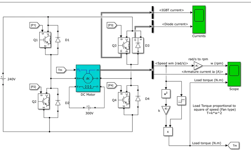
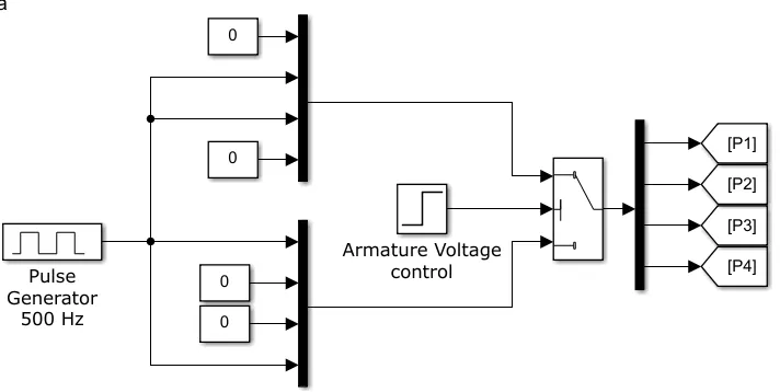
Block description:
An IGBT is used here since the BJT operates as IGBT when used for power switching applications.
The switch is ON when a forward voltage is applied between collector and emitter (in the range of 1V). The switch is controlled by a Simulink signal (1/0)
The DC motor uses the preset model (5 HP 24V 1750 rpm). It simulates a fan type load (where Load torque is proportional to square of speed). The armature mean voltage can be varied from 0 to 240 V when the duty cycle (specified in the Pulse Generator block) is varied from 0 to 100%.
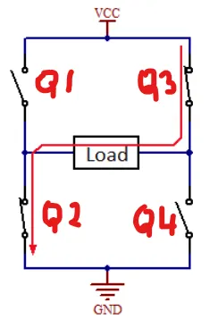
The H-bridge consists of four BJT/Diode pairs (BJT simulated by IGBT models).
Two transistors are switched simultaneously: Q1 and Q4 or Q2 and Q3. When Q1 and Q4 are fired, a positive voltage is applied to the motor and diodes D2-D3 operate as free-wheeling diodes when Q1 and Q4 are switched off.
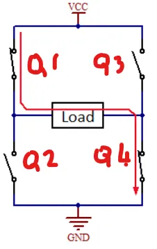
When Q2 and Q3 are fired, a negative voltage is applied to the motor and diodes D1-D4 operate as free-wheeling diodes when Q2 and Q3 are switched off.
Simulation
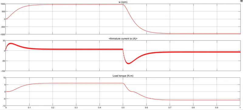
The motor starts in the positive direction with a duty cycle of 75% (mean DC voltage of 180V).
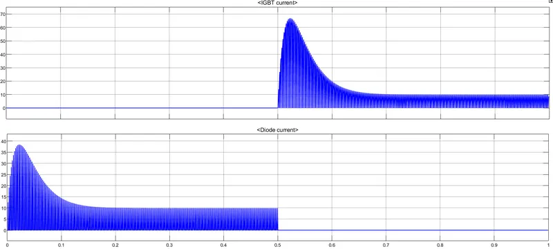
The switches Q1 and Q4 are ON. Q3 and Q2 are off. D2 and D3 acts as free wheeling diode.
At t= 0.5 sec., the armature voltage is suddenly reversed and the motor runs in the negative direction.
The switches Q2 and Q3 are ON. Q1 and Q4 are off. D1 and D4 acts as free wheeling diode.
1)b) Armature current shoot up:

The armature current spikes at each duration of switching when the armature voltage is reversed.
This is due to the transient switching between the two states of positive and negative voltage applied to the motor instantenously. This switching causes the input-surge current or inrush currents. The maximum instantaneous input current drawn by an electrical device when first turned on is known as Inrush current.
1)c)The Four-Quadrant Chopper DC Drive (DC7) block:
The complete simulation on a 200 HP four quadrant chopper DC drive is shown below:
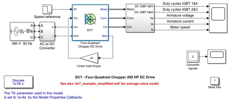
The varous blocks build under the four quadrant chopper DC drive block is shown below:
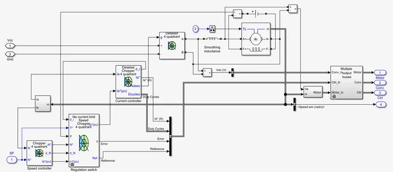
The 200 HP DC motor is separately excited with a constant 150 V DC field voltage source.
The armature voltage is provided by an IGBT converter controlled by two PI regulators. The converter is fed by a 515 V DC bus obtained by rectification of a 380 V AC 50 Hz voltage source.
In order to limit the DC bus voltage during dynamic braking mode, a braking chopper has been added between the diode rectifier and the DC7 block.
The first regulator is a speed regulator, followed by a current regulator. The speed regulator outputs the armature current reference (in p.u.) used by the current controller in order to obtain the electromagnetic torque needed to reach the desired speed. The speed reference change rate follows acceleration and deceleration ramps in order to avoid sudden reference changes that could cause armature over-current and destabilize the system.
The current regulator controls the armature current by computing the appropriate duty ratios of the 5 kHz pulses of the four IGBT devices (Pulse Width Modulation). For proper system behaviour, the instantaneous pulse values of IGBT devices 1 and 4 are opposite to those of IGBT devices 2 and 3. This generates the average armature voltage needed to obtain the desired armature current. In order to limit the amplitude of the current oscillations, a smoothing inductance is placed in series with the armature circuit.
Comparison :
| H - Bridge | Four Quadrant chopper Dc drive |
| Works on a fixed DC supply | Works on a AC supply which is rectified by a diode rectifier |
| Does not provide speed or current regulation | Provides both speed and current regulation |
| Occurence of current surges due to the inrush currents during switching | Prevents the current surges by placing a smoothing inductance in series with the armature circuit |
| Two quadrant operation only available. Forward and reverse motoring | Four quadrant operation such as Forward motoring, reverse motoring, Forward braking and Reverse braking are available. |
2)Two quadrant chopper simulink model:
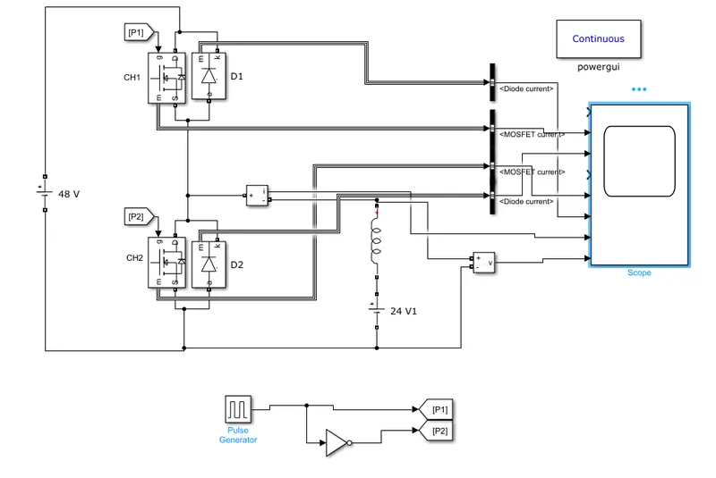
The simulink model of two quadrant chopper is shown below: The operation is on first and second quadrant
During the first quadrant of operation: When CH1 is on --> Positive current flows from source to load, Output load voltage will be the source voltage
When CH1 is OFF --> D2 conducts and the same positive current flows through D2, Inductor and V1
Both Voltage and current are positive and hence lies in the first quadrant
During the second quadrant of operation: When CH2 is ON --> The stored energy in the inductor flows as negative current flows through Inductor, CH2 and V2
When CH2 is OFF --> The negative current takes the path of Inductor, D1 and Source voltage V (Regererative Braking mode)
Current is negative but voltage is positive. Hence lies in the second quadrant
Results of the Simulink model:
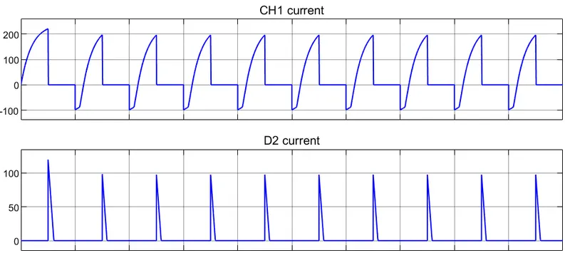
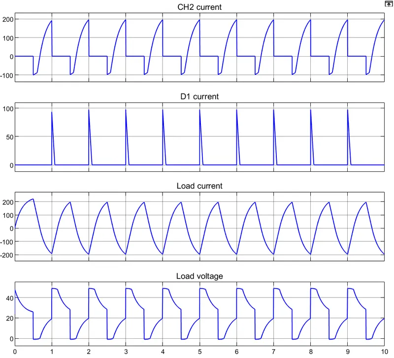
Conclusion: We can find that when CH1 is ON, the current is positive and the output voltage is the source voltage. When CH1 is off the diode D2 conducts until the current becomes zero and CH2 is ON.
When CH2 is ON, the current becomes negative and the output voltage is zero. When CH2 is OFF, D1 conducts until the current becomes zero again or until CH1 becomes on again.
3)Operation of BLDC motor:
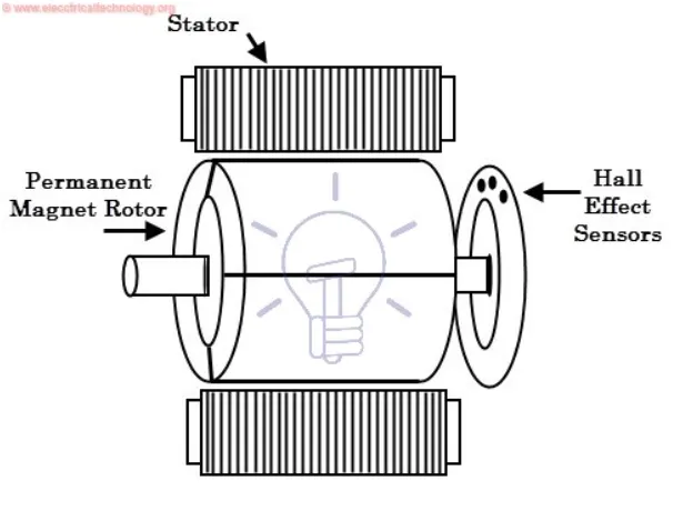
A brushless DC motor (known as BLDC) is a permanent magnet synchronous electric motor which is driven by direct current electricity and it accomplishes electronically controlled commutation system (commutation is the process of producing rotational torque in the motor by changing phase currents through it at appropriate times) instead of a mechanically commutation system. BLDC motors are also referred as trapezoidal permanent magnet motors.
Unlike conventional brushed type DC motor, wherein the brushes make the mechanical contact with commutator on the rotor so as to form an electric path between a DC electric source and rotor armature windings, BLDC motor employs electrical commutation with permanent magnet rotor and a stator with a sequence of coils. In this motor, permanent magnet (or field poles) rotates and current carrying conductors are fixed.
The armature coils are switched electronically by transistors or silicon controlled rectifiers at the correct rotor position in such a way that armature field is in space quadrature with the rotor field poles. Hence the force acting on the rotor causes it to rotate. Hall sensors or rotary encoders are most commonly used to sense the position of the rotor and are positioned around the stator. The rotor position feedback from the sensor helps to determine when to switch the armature current.
This electronic commutation arrangement eliminates the commutator arrangement and brushes in a DC motor and hence more reliable and less noisy operation is achieved. Due to the absence of brushes BLDC motors are capable to run at high speeds. The efficiency of BLDC motors is typically 85 to 90 percent, whereas as brushed type DC motors are 75 to 80 percent efficient.