Week-7 Challenge: DC Motor Control
1. AIM : Understand DC motor control components and Explain it with an example.
2. OBJECTIVES OF THE PROJECT :
Give the answer to the below questions to complete the challenge:
A. a. Explain a MATLAB demo model named ‘Speed control of a DC motor using BJT H-bridge’.
b. Comment on the armature current shoot-up from the scope results.
c. Refer to the help section of ‘The Four-Quadrant Chopper DC Drive (DC7) block’. Compare it with the H-bridge model.
B. Develop a 2-quadrant chopper using simulink & explain the working of the same with the relevant results. (Refer to article - Multiquadrant operation of motor )
C. Explain in a brief about operation of BLDC motor.
3.GOVERNING EQUATIONS IF ANY:
4.BODY OF THE CONTENT:
_____Answers of the Questions:
_____Ans. 1-A:
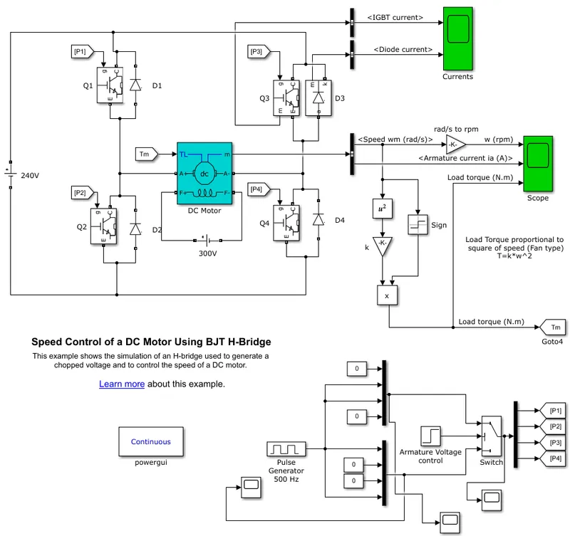
Fig : 01 Speed control of a DC motor using BJT H-bridge
Let's start with common but important block -
Powergui block `rArr` Required to Simulate any Simulink model containing Simscape™ Electrical™ Specialized Power Systems blocks.
Generating Simulink Signal `rArr` Generating signals for IGBT switches using 'Pulse Generator block' that create a signal of 500Hz. where, Amplitude : 1, Period (secs): 2e-3 (0.002), Pulse Width (% of period): 75, Phase delay (secs): 0. This generates a signal as per below, for time 1 sec (see fig.02). Then using a 'Mux' adding two 500Hz and two zero signals in two different 'Mux' blocks to operate four switches. This 'Mux' block output is going into 'Switch' block'. where it is operated by 'step' block with step time(0.5), Initial value(0), Final value(1), simple time(0). And 'Switch block. threshold value is 0.5. So, switch will on for 0.5sec & off for 0.5sec. And using 'Demux block' Separating all four signal from 'Switch' output and giving it connection as an input to 'IGBT' switch using 'From' & 'Goto' block.
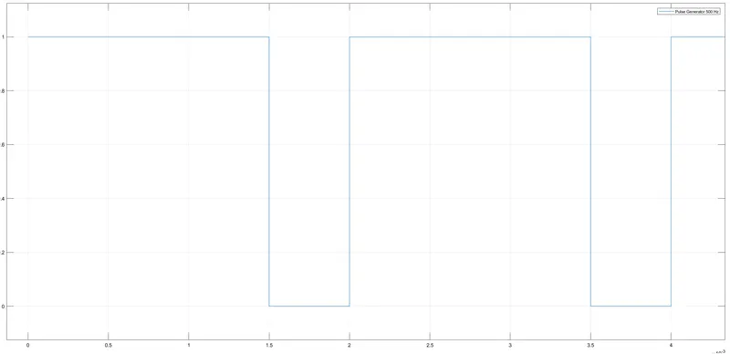
Fig : 02 Pulse Generator 500Hz (scale view : `x`- axis scale `->` x `10^(-3)`)
IGBT switch `rArr`The Bipolar Junction Transistor (BJT) when used for power switching applications, operates as an IGBT. When it is conducting (BJT operating in the saturated region), a forward voltage Vf is developed between collector and emitter (in the range of 1 V). Therefore, the IGBT block can be used to model the BJT device. In Simulation four IGBT switches (Q1, Q2, Q3, Q4) were used to run the motor forward and backward. This type of system arrangement is called H-bridge. Each switches has an Diode (D1, D2, D3, D4) to prevent current flow in reverse direction. where, 240 V source connected to switches as per motor input requirement. Using 'Bas selector' Diode and IGBT current value extracted. (see fig 03). From fig we can see that on the initial level where the motor starts in a positive direction it is taking the highest current of 38A (refer Diode current). But when suddenly it start to rotate in opposite direction will take highest 66A (refer IGBT current).
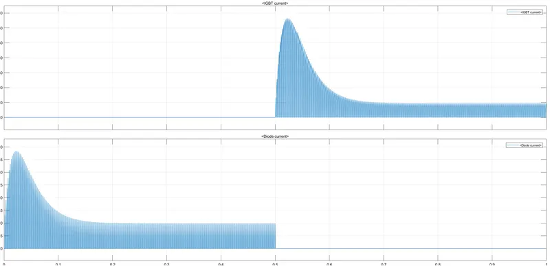
Fig : 03 IGBT (Q3) & Diode current (D3)
DC motor `rArr`In this case 5hp, 240v, 1750rpm, Field:300V 'wound-field motor' selected with their default values. To provide voltage to the field, separate 'voltage source' selected of 300V. Here pulse width 75% of period so, Armature will receive 180V. Mechanical input 'Torque' is selected.where, Load torque is proportional to square of speed. and the initial speed is default 0.001 selected. As the motor has H-bridge connection with switches it will rotate forward for 0.5 sec, then reverse for 0.5 sec. Extracting motor data using 'busselector' and speed, armature current plotted via scope in 'RPM' and 'A' respectively. From motor speed reference torque value is calculated using square, gain, signum and product block. where, T=k*w^2, k is torque constant. And using 'From'-'Goto' block torque taken as input value.
As per fig.04 we can see that, via a positive signal motor,current and torque values get positive. after getting in negative.
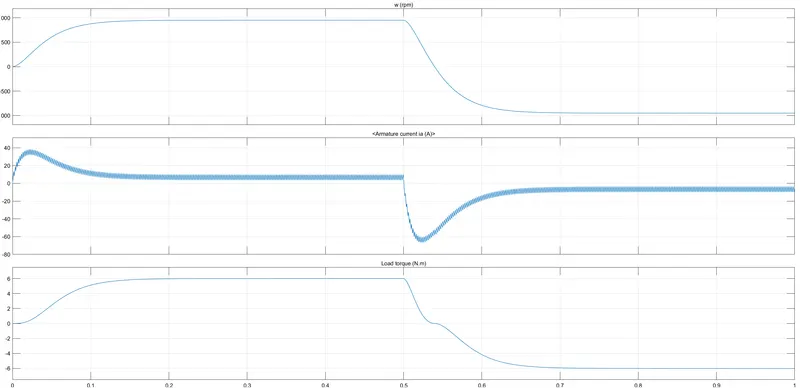
Fig : 04 DC motor output
_____Ans. 1-B: Based on motor inertia, input voltages and due to some other factors, the motor takes some time to get full speed and stable condition (~0.2 sec). As per natural law of force to move an object at initial level requires a higher amount of energy. We can see it here. At the initial level in the positive direction the motor gets current(36A). then it's going to be constant(~10A). and when the current is going to reverse its taking higher current (~66A). then it's going to be constant(~-10A). Reasons to get higher ampere due to power is used to first stop positive rotation of the shaft(~0.04sec) and then rotating in negative direction(~0.16sec).
_____Ans. 1-C: Refer to the help section of ‘The Four-Quadrant Chopper DC Drive (DC7) block’. Compare it with the H-bridge model.
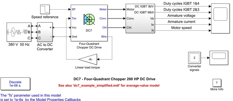
Fig : 05 DC7 - Four-Quadrant Chopper 200 HP DC Drive
The Comparison will be,
| DC7 - Four-Quadrant Chopper 200 HP DC Drive v/s Speed control of a DC motor using BJT H-bridge | |
| `rarr` It has 200 hp 440V 1184 RPM, Field:150V DC drive motor with 'NO' preset model. | |`rarr`It has 5 hp 240V 1750 RPM, Field:300V |
| `rarr`For input 380V 50 Hz 3Phase power supply selected, then converted to DC power. | |`rarr`For input 240V Ideal DC voltage source selected. |
| `rarr`Motor Speed Controlled by controlling current using IGBT switches. | `rarr`Motor Speed Controlled by controlling current using IGBT switches. |
| `rarr`It is a one type of a Close Circuit Example. Where Current controller, Speed controller, Regulation switch. | `rarr`It is a one type of Open Circuit Example. |
| `rarr`There is a One ‘Universal Bridge’ block used to perform Forward and Reverse moments of the motor. | `rarr`There are four simple IGBT blocks used to perform Forward and Reverse moments of the motor. |
| `rarr`Complex System to understand | `rarr`Simple System to understand. |
_____Ans. 2: 2-Quadrant Chopper using simulink, as below,
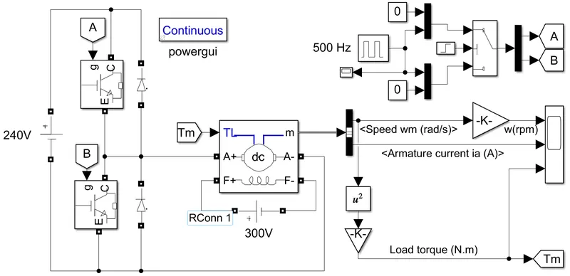
Fig : 06 DC7 - Two-Quadrant Chopper 5HP DC Drive
Here a simple model created to explain 2-quadrant operation. Where 5hp, 240V, 1750 rpm motor selected.
Using "Plus Generator" 500 Hz single generated in time 1 sec. Using "Switch" and "Step" block digital signals created for 2 IGBT switches. Where 0.5 IGBT 'A' will be active and the next 0.5 sec IGBT 'B' will be active. Using 'Demux block' signal is separated of IGBT. Using a DC voltage source, IGBT switch, Diode, DC machine a Two-Quadrant Chopper model was created. In DC machine as mechanical input 'Torque' is selected And its calculated as per this equation.`( T = w^2*k).` Using 'Bus collector speed and armature current extracted.
For First quadrant 'DC voltage source' > 'IGBT switch A' > 'DC machine' creating a close loop and motor will give an output with respect to input. And 'IGBT switch B' > DC machine creating loop for 2nd quadrant. Here First quadrant represents 'Forward motoring' and Second represents 'Forward Braking'.
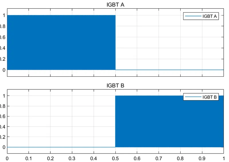
Fig : 07 IGBT signal input
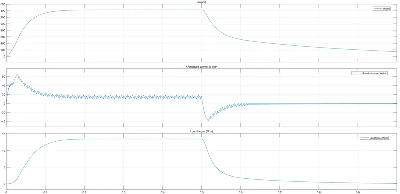
Fig : 08 Output of 5HP DC Drive
As per output we can see that for 0 to 0.5 sec Getting positive value of Torque and Current(First quadrant), then for 0.5 to 1 sec getting torque positive but current is negative(2nd quadrant). As we can see in (fig: 07) 2nd quadrant 'IGBT B' will turn on and we stop to giving voltage input to motor but still getting current. Here we are not giving any external input for stop motor rotating, Still it is in running condition due to load torque effect. Can see the negative value of current. Later It will stop slowly by itself after sometime.
_____Ans. 3: Brief about operation of BLDC motor,
As their name suggests, brushless DC motors do not have brushes. Here Rotor has a Permanent magnet and coils are fixed in place. Because the coils do not move, there is no need for brushes and a commutator. Here a permanent magnet that rotates; rotation is achieved by changing the direction of the magnetic field that is generated by the fixed coils. To control the magnetic field we have to adjust the magnitude and direction of the current into fixed coils.
One of its advantages is higher efficiency with respect to brushed motors. Another is a controllability using feedback mechanism, that delivers precisely the desired torque and rotation speed. It's also offers high durability and low electrical noise.
REFERENCES :
- https://www.fluke.com/en-in/learn/blog/electrical/what-is-a-
- What is a Diode? | Fluke.
- Half wave Rectifier with a Capacitor Filter and Ripple Factor Calculation
- The PN Junction | Solid-state Device Theory | Electronics Textbook
- H-Bridge Motor Driver Using Bipolar Transistors
- Diodes and its type.
- What is Four Quadrant Operation of DC Motor? - Speed Torque & Power Relationship - Circuit Globe.
- Types of Chopper Circuits - Type A, Type B, Type C, Type D, Type E