Week-7 Challenge: DC Motor Control
1)
A) We can access 'Speed Control of a DC Motor Using BJT H-Bridge' model from Matlab command window by using the command 'power_Hbridge'.
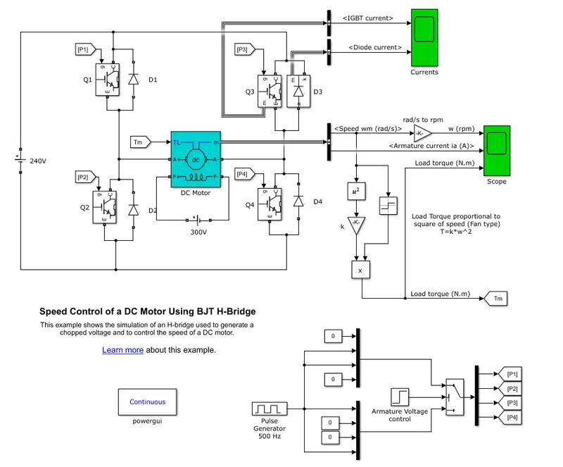
From the model we can see a Voltage source, PWM model, H-bridge Circuit, DC motor and a load. For a DC motor to work in both forward and reverse conditions an H-Bridge driver circuit is used. Here the H-bridge circuit is made up of 4 BJT (Bipol Junction Transistor) switches namely Q1,Q2,Q3 and Q4 respectively. For a motor to work in both motoring as well as generating mode motor need to rotate in both clockwise as well as counter clockwise direction. This can be done by changing the polarity across the motor, which can be achieved by proper switching. PWM generator generates the pulses for the BJT so as to turn on and off the device in a sequential manner. Here with respect to the figure, PWM generates the pulses of same frequency which is given to 2 (4*1) MUX and inturn given to a switch. The switch is connected to a (1*4) DEMUX which gives the pulses to the gate of 2 switches such that triggering the BJT switches. In the H-bridge circuit 4 BJTs along with 4 diodes are provided, when Q1 and Q4 are triggered then the flow of current across the motor will be from positive to negative and D2 and D3 diodes acts as free-wheeling diodes. This means the motor is rotating in forward direction. Now when Q2 and Q3 are triggered the polarity accross the motor changes and the motor rotates in reverse direction. D1 and D4 diodes acts as free-wheeling diodes. Hence forward motoring and reverse motoring mode are achieved. Due to the constraints in using BJT switches braking modes cannot be achieved. The output of the motor is connected to a fan-type load.
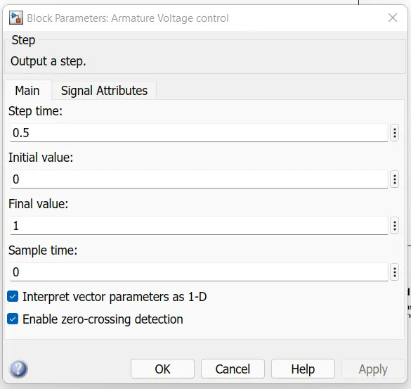
Armature voltage control block in PWM model shows the step time as 0.5, indicating switching happens at 0.5 step time or polarity across the motor reverses and motor rotates in reverse direction. The output of the simulation are obtained as:
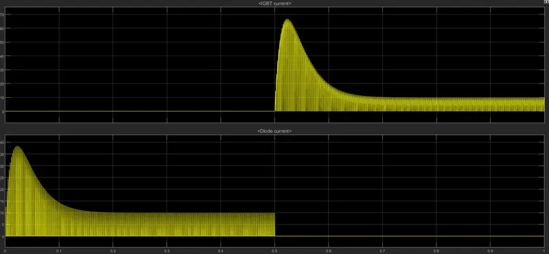
Here the currents from Q3 BJT and D3 diode are shown. During the first 0.5 step time Q3 is not triggered and D3 acts as free wheeling diode hence no current flows through Q3. After 0.5 step time Q3 is triggered and hence current flows through Q3.
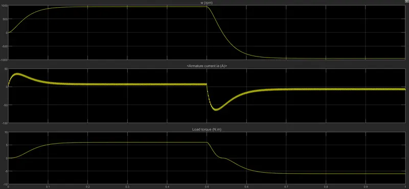
Here the Speed, Armature current and load torque is shown. The speed shows a shift towards negative direction after 0.5 step time as polarity is changed across DC motor or as Q2 and Q3 are triggered. We can observe similar patterns in Armature current and Load torque. Negative current indicates the motor acting as a generator.
B) A shoot up is observed for the armature current at starting, this can be explained in terms of Back-emf and speed of the DC motor.

We know that for a DC motor;
Ia=(V-Eb)/Ra
where Ia is the armature current, Eb is the back-emf or counter emf, V is the input DC voltage and Ra is the armature resistance.
During starting or at 0 step time, Back-emf Eb is zero as speed is 0. Hence without the back-emf the equation becomes V/Ra. As we know the armature resistance is very low for the DC motor, Ia is very high, and hence the shoot-up. In other words, High starting currents are observed in DC motors and to prevent damage to the components Starters are used. They provide external resistance to the motor such that it acts as a series connection with armature winding of Motor.
C) A chopper is a static device which converts DC into variable DC input or known as a DC-DC converter which is widely used to achieve motor control and regenerative braking. Here the working principle is switching by interupting one signal under the control of another. This may cause voltage and current spikes across the circuit, hence we use snubber RC circuit. The snubber circuit protects the circuit from voltage spikes due to sudden change in current. Spikes may be caused by transients due to continuous switching.
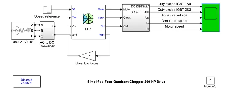
The figure shows a simulation model of four quadrant chopper with a DC motor. The working of chopper circuit in four qudrant mode can be explained by;
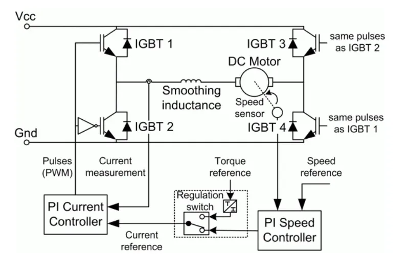
Forward Motoring Mode: Here 1 & 4 are triggered, the current flows through 1 & 4 and the inductance stores the energy. As the load current and armature current have same polarity the motor rotates in forward direction. When 1 is OFF the energy stored flows to 4 by through D2. (Quadrant 1)
Forward Braking Mode: Here 2 is triggered, current flows through 2 and D4 in reverse direction. The motor rotates in reverse direction. If 2 is off the energy stored flows through D4 and D1. (Quadrant 2)
Reverse Motoring Mode: Here 2 and 3 are triggered, current flows through 3 to 2 in reverse direction. When 3 is off, current flows through 2 and D4.(Quadrant 3)
Reverse Braking Mode: Here 4 is triggered, current flows through D2 to 4 in positive polarity. When 4 is off, current flows through D2 and D3.(Quadrant 4)
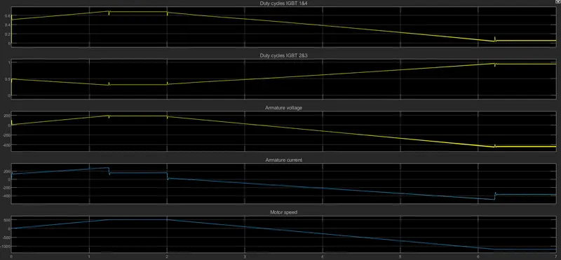
The simulation result of the above model shows the working of the model through out the quadrants. Here the armature current is positive during the Forward motoring and Reverse braking modes and negative in Forward braking and reverse motoring mode. the voltage is negative only in Reverse motoring and Reverse braking modes.
Comparing the Chopper model with H-bridge model, we can see that in H-bridge model we only change the polarity by switching, whereas in Chopper model one signal in interupted while controlling another. Snubber RC circuits are used to protect the system from spikes caused by transients due to switching in Chopper circuits. we don't require such snubber circuits in H-bridge model. Braking modes are not possible with H-bridge circuit whereas it is achieved with Chopper circuits. Both have its own application and advantages. H-bridge is commonly used in robotics while choppers are used mainly for motor control and regenerative braking. H-bridge circuit is much simpler compared to Chopper circuit.
2)
2 Quadrant Chopper also known as Type C choppers are choppers that works on first as well as the second quadrant. Which means the power can either flow from source to load or from load to source.
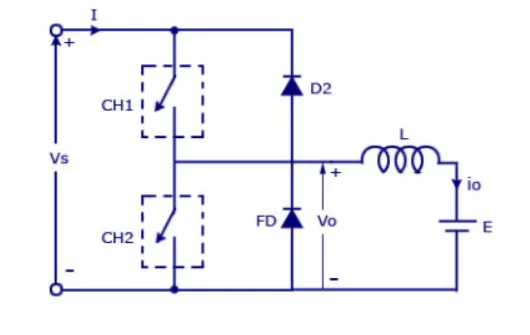
The working of a Type C chopper is a combination of Class A and Class B choppers that works in 1st and 2nd quadrant respectively. Type C chopper is obtained by the parallel connection between class A and class B choppers. In this type of chopper the average voltage will always be positive but the current can be positive or negative. When the two switches CH1 and CH2 are turned on simultaniously it causes a short circuit hence not preferable. This type of configuration is used for regenerative braking and motoring mode.
When CH1 is turned on and CH2 off; Source Vs directly gets connected to the load and hence, load voltage Vo is equal to source voltage. The direction of load current is from source to load as shown in the circuit diagram which is positive. When CH1 is switched OFF, the free-wheeling diode FD comes into the circuit as it gets forward biased and hence shorts the circuit. Therefore, the output voltage Vo becomes zero. However, the io continues to die down through the FD and L in the same direction as shown in circuit diagram. Thus, the average output voltage Vo and current Io are positive and hence operation of chopper is in first quadrant. In fact, this is the Class-B mode of operation.
When CH2 is turned on and CH1 off: When chopper CH2 is switched ON, load DC source E drives current through CH2 and load. The direction of this current io will be opposite to that shown in circuit diagram and hence is assumed negative. Output voltage Vo is zero during this time. When CH2 is made OFF, diode D2 gets forward biased and hence the current into the source from the load. The output voltage is Vs in this time as the load is connected to the source through D2 during OFF time of chopper CH2. Thus, the load current is always negative i.e. operation of chopper is within second quadrant. In fact, this is the Class-B mode of operation.
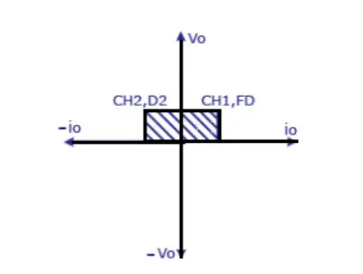
The operating region of Class-C or Type-C chopper is shown below by hatched area in the above figure. From the circuit, the simulink model can be obtained as:
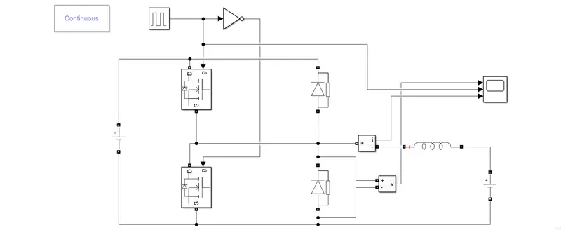
Here two mosfets are chosen as switches connected with two diodes. The gate pulse given to one of the mosfets in through a NOT logic such that both switches aren't triggered simultaniously forming a short circuit. The input voltage is given to be 24 V and E is given as 12 V. The amplitude of the PWM pulses are given as 10. The output obtained is as follows:
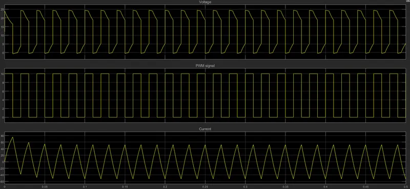
Here we can see that the current going negative, whereas the voltage is always positive showing the 2 quadrant operation. The pulses are provided such that the switches does not form a short circuit. Hence 2-Quadrant Chopper is simulated and verified.
3)
A brushless DC electric motor (BLDC motor or BL motor), also known as electronically commutated motor and synchronous DC motors, are synchronous motors powered by direct current (DC) electricity. As their name suggests, brushless DC motors do not use brushes. Whereas with brushed motors, the brushes deliver current through the commutator into the coils on the rotor. Here the rotor is a permanent magnet and the coils here do not rotate, but are fixed instead in place on the stator. Because the coils do not move, there is no need for brushes and a commutator. With the brushed motor, rotation is achieved by controlling the magnetic fields generated by the coils on the rotor, while the magnetic field generated by the stationary magnets remains fixed. To change the rotation speed, we need to change the voltage for the coils. With a BLDC motor, it is the permanent magnet that rotates; rotation is achieved by changing the direction of the magnetic fields generated by the surrounding stationary coils. To control the rotation, you adjust the magnitude and direction of the current into these coils.
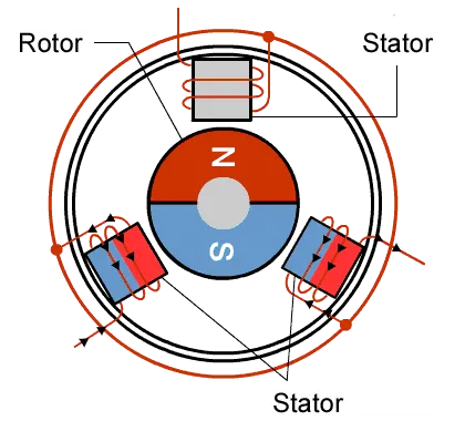
A permanent Magnet AC motor, which has a trapezoidal back emf, is referred to as brushless DC motor (BLDC). The BLDC motor requires quasi-rectangle shaped currents. Alternatively, the voltage may be applied to the motor every 120°. Because the phase currents are excited in synchronism with the constant part of the back emf, constant torque is generated. The electromagnetic torque of the BLDC motor is related to the product of phase, back emf and current. The back emf in each phase are trapezoidal in shape and are displaced by 120 electrical degree with respect to each other in 3 phase machine. A rectangle current pulse is injected into each phase so that current coincides with the back emf waveform thus the motor develops an almost constant toque.
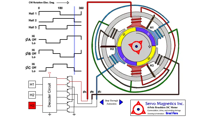
Hall Effect sensor provides the portion of information needed to synchronize the motor excitation with rotor position in order to produce constant torque. It detects the change in magnetic field. The rotor magnets are used as triggers to the Hall Sensor. Three Hall Sensors placed 120° apart, are mounted on the stator frame. The Hall Sensor digital signals are used to sense the rotor. A BLDC motor with three coils on the stator will have six electrical wires (two to each coil) extending from these coils. In most case three of these wires will be connected internally, with the three remaining wires extending from the motor body.
The advantage of BLDC motor is its efficiency, as these motors can control continuously at maximum rotational force (torque). Brushed motors, in contrast, reach maximum torque at only certain points in the rotation. For a brushed motor to deliver the same torque as a brushless model, it would need to use larger magnets. This is why even small BLDC motors can deliver considerable power.The second advantage is its controllability. BLDC motors can be controlled, using feedback mechanisms, to delivery precisely the desired torque and rotation speed. BLDC motors also offers high durability and low electric noise generation due to the lack of brushes. With brushed motors, the brushes and commutator wear down as a result of continuous moving contact, and also produce sparks where contact is made. Electrical noise, in particular, is the result of the strong sparks that tend to occur at the areas where the brushes pass over the gaps in the commutator. In BLDC electrical as well as the mechanical voices are reduced.