Week-6 Challenge: EV Drivetrain
1)
A power converter is an electrical or electro-mechanical device used for converting one form of electrical energy to another desired form. A power converter can do a variety of functions such as converting alternating current to direct current or vice-versa and can also change the frequency or voltage for the current. In Electric and Hybrid electric vehicles these power converters are responsible maintaining power continuity. Some of the major power converter components used in electric or hybrid vehicles are inverters, rectifiers/converters and on- board chargers. These power electronic devices improves the efficiency and make the system capable of working at high voltage because of their high switching frequency.
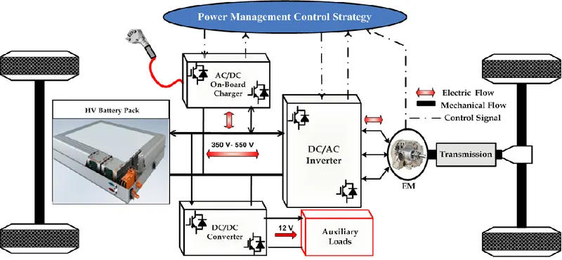
Power coverters used in EV and HEV can be catagorized as:
i) AC to DC Converter
This type of converters are usually known as Rectifiers which converts AC power supply to DC. The main application of these type of converters are for Battery in an EV and HEV. During charging of battery that is during regenerative breaking the power from the generator is in the form of AC and it need to be converted into DC inorder to store the energy in battery. For PHEV these converters are used when charging the battery from a charging station or from home. These converters are present in the on-board charger which is directly connected to the battery which converts 230V, 50 hz AC supply to the suitable DC supply for the battery pack.
ii) DC to AC Converter
This type of converters are usually known as Inverters which convert DC power into AC. They are usually used for providing power for motor driving application. The power from the battery (DC) is converted into AC for the motor to drive IN EVs and HEVs. The inverter can control the rotation of the motor by adjusting the frequency of the alternating current. It can also power auxillary roads which works on AC.
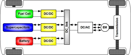
iii) DC to DC Converter
This type of converters are usually known as Choppers. Here the level of the DC voltage is converted i.e, we can convert a 120V DC supply to 12V DC supply by using a chopper. Here the DC to DC converters are used for linking the DC sources to a DC bus or to power auxillary loads. Choppers act as a protective device to certain components which are sensitive to high or low voltages.
iv) AC to AC Converter
This type of converters are known as regulators. Here the input AC waveform with particular voltage and frequency is converted into another AC waveform with different voltage and frequency. They are used in EVs and HEVs as regulators for Lamps (dim and bright), Air Conditioners and to control motor speed.
2)
Given:
Motor and Controller Parameters:
Rated Armature voltage= 72 V
Rated armature current= 400 A
Ra= 0.5Ω
KΦ= 0.7 Volt second
Chopper Switching frequency= 400 Hz
The vehicle speed-torque characteristics are given by:

Duty cycle = 70% = 0.7
At 0.7 Duty Cycle,
Voltage = Rated Armature voltage x Duty Cycle = 72 x 0.7 = 50.4 V
The torque speed characteristics of a DC motor is given by:
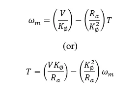
Where T is the motor torque, V is the voltage, Ra is the armature current, KΦ is the motor constant and ωm the angular speed of the motor.
Therefore;
T = ((50.4 x 0.7)/0.5)-((0.7²/0.5)x ω) = 70.56 - 0.98ω .....(1)
given Tv = 24.7 + 0.0051ω² ......(2)
Comparing (1) & (2);
70.56 - 0.98ω = 24.7 + 0.0051ω²
0.0051ω² + 0.98ω - 45.86 = 0 ......(3)
Inorder to find solution of this Quadratic equation we can use the standard formula;
i.e, x = (-b ± √(b² - 4ac))/2a
Here a= 0.0051, b= 0.98 and c=-45.86
ω= (-0.98 ± √(0.98² - 4x0.0051x-45.86))/2x0.0051
we get ω = 38.914 rad/s and ω = -231.071 rad/s
Since speed value is always positive we get ω = 38.914 rad/s
Therefore, EV steady state speed at duty cycle 70% is 38.914 rad/s.
3)
We have the mathematical model of a dc moter defined by the equation:
Where T is the motor torque, V is the voltage, Ra is the armature current, KΦ is the motor constant and ωm the angular speed of the motor.
In simulink by using Constant blocks for V, Ra, KΦ and T, a set of divide and product blocks and a an adder block we could implement the equation in Simulink. A display block from simulink library is used to show the ω as output.
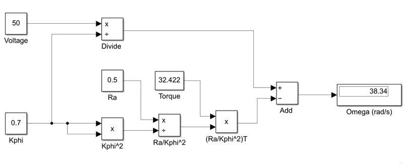
Here we are giving V as 50 V, KΦ as 0.7, Ra as 0.5 and Torque as 32.422, and we get the value for ω which is 38.34 rad/s.
4)
From the authors perspective brushless DC motors and induction motors will be used for a certain golden era unlike its predecessor brushed dc motors because of the merits these two have in the industry. Both of the models are way similar in hardware and have its own properties when performance is considered. The rotor of BLDC have 2 or more permannent magnets that produce a magnetic field., when this magnetic field interacts with the stator winding torque is produced. For the continuity in rotation of rotor, the polarity of the stator current need to be continuosly varied. The current control in BLDC is mainly done by an inverter, this is the working of BLDC motor. Coming to Induction motor it doesnt have any magnets, they are stacked laminations with buried conductors. current through stator winding produces a rotating magnetic field that interacts with the rotor. a voltage is induced in the rotor which is proportional to the speed difference of rotor and electrical frequency. When current interacts with this magnetic field it produces forces.
Similarity between BLDC and Induction motor are that the stators are virtually identical and they both have 3 sets of distributed windings. Difference between BLDC and induction motor lies in the rotor as mentioned. Induction motor doesnt require any inverter circuitary and can directly work from utility power. while working in utility power it becomes a constant speed machine since the frequency is constant. An induction motor can work from a battery or DC source with the help of an inverter and for variable frequency appication the onvertery frequency can be altered.
With the advancement to digital controllers the difference is between the control code, BLDC requires a position sensor whereas induction motor requires a Speed sensor. BLDC has it own advantages susch as less rotor heat is generated. In practical case, adjustment of permanent magnets magnetic field strength is not possible for low and high torque to reduce losses. Induction motors doesnt have any magnets and hence magnetic field strength are adjustable since B is proportional to v/f. Permenant magnents are expensive are difficult to handle. thus induction machine always have a cost advantage over BLDC. But induction machines are more difficult to control. From the authors perspective both the motors have its own uses, BLDC will be usefull in case of HEV and PHEV whereas induction motors will be more used in high performance pure EV for an unforeseen period in the future mentioned by a golden era.