Project-1: Powertrain for aircraft in runways
PART A:
1)
The idea of aircraft was coined long before when people thought of flying for themselves. However, it wasn't until 1903 that the Wright Brothers, two bicycle store proprietors, achieved the first manned flight and created the first operational plane. Since then, airplane has brought the world closer together by making travel easier than ever before. People can travel across the world in less than a day and visit many nations in the same day. There has never been a time when the world has been so small. The race to develop quicker, more efficient aircrafts continues to this day. Based on the weight of the air crafts they are classified as:
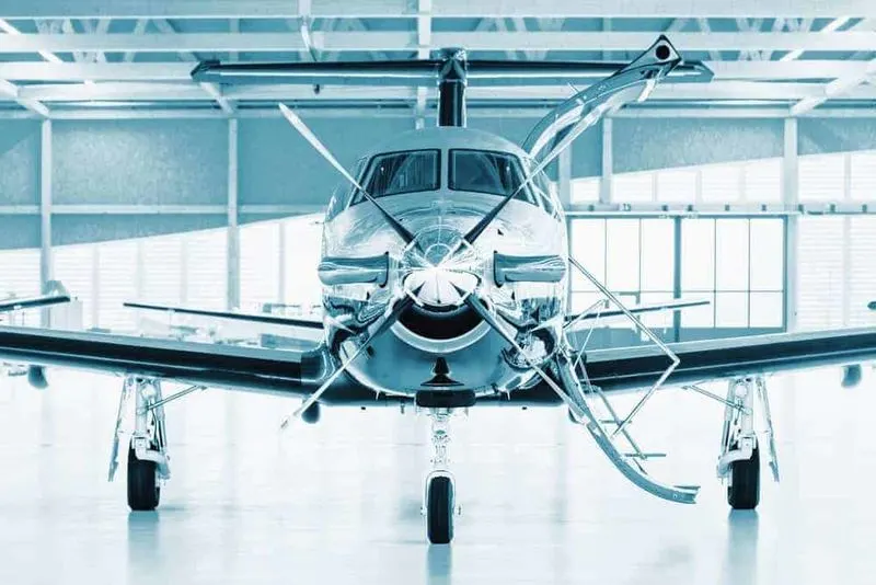
Turboprop Aircraft:
One or more gas turbine engines power the turboprop aircraft. Both are linked to a gearbox that drives the propellers. This is in contrast to the piston or jet engines used in other types of small planes. Turboprop planes are typically significantly larger than piston planes and can fly at much higher heights than piston planes, up to 35,000 feet. They're well-suited to flying 600 to 1000 miles in a single flight and are a significantly less expensive alternative to private jets. Turboprop aircraft weighs about 42000kg or 92000 pounds.
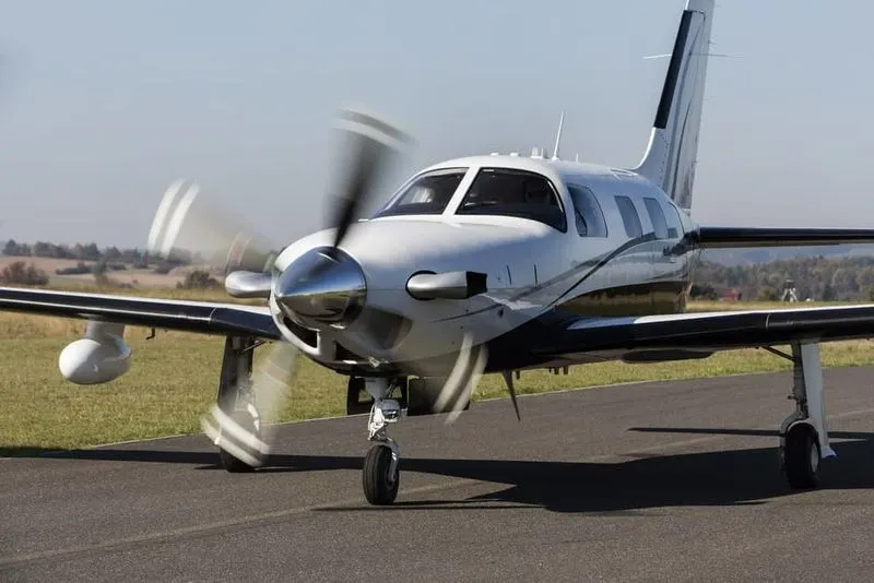
Piston Aircraft:
They are similar to Turboprop aircrafts but are smaller. They also feature one more piston-powered engine attached to the propellers. They're also incapable of flying at the same high altitudes as turboprop planes (15,000 feet) and can only cover a fraction of the distance (300 to 400 miles). The conventional piston aeroplane may seat one to six people in two-row rows. Piston aircraft do not require extensive runways or traffic control towers in order to fly. The maximum take-off weight of a piston aircraft is around 2000kg.
Jets:
Jets are well known for their speed and power as compared to other aircrafts. They are most efficient at high speeds and can even travel at supersonic speeds (faster than the speed of sound). Jet planes can travel at speeds of roughly Mach 0.8 (609 mph) and fly at altitudes of 49,000 feet. Jets were first developed in England in 1928, but they were perfected in Germany in 1936, when Ernst Heinkel spearheaded the development of the first jet plane. The jets weigh around 40,000 kg or 90,000 lbs.
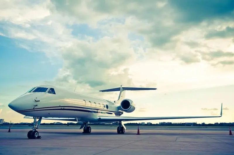
Light Jets:
The most popular form of hired plane among company owners is a light jet plane. These are sometimes options for folks who want to travel on a budget but don't want to fly in a turboprop. For short travels and light luggage, these are the most cost-effective option. The maximum take-off weight of a light jet is around 10,000 pounds or 4500kg.
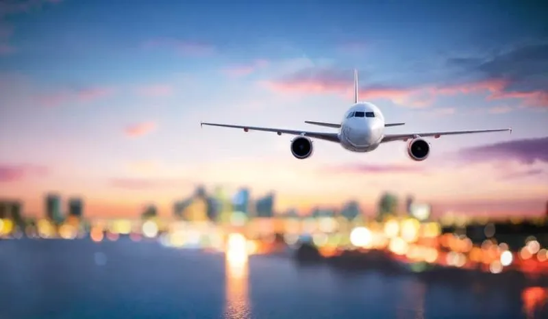
Jumbo Jets:
Heavy jets offer the best of both worlds in terms of range and space. They provide far greater opportunities than their tiny equivalents. They're only for lengthy hauls and journeys. There are also ultra-long-range heavy jets available for VIP charters with the highest level of luxury. Their maximum takeoff weight ranges from 735,000 pounds (333,400 kg) to 970,000 lb (439,985 kg).
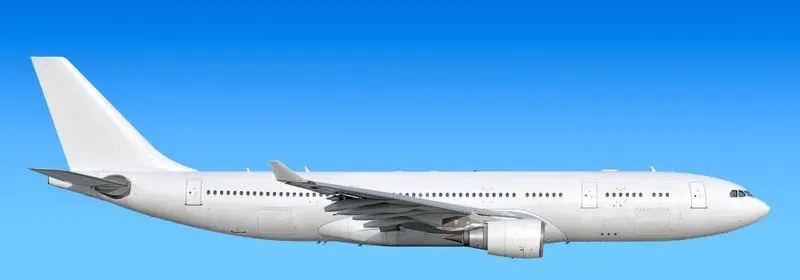
Helicopter:
A helicopter is a rotorcraft with horizontally spinning rotors that provide lift and thrust. The helicopter can take off and land vertically, hover, and fly forward, backward, and laterally as a result of this. Because of these characteristics, helicopters can operate in congested or isolated regions where fixed-wing aircraft and many types of STOL (Short Takeoff and Landing) or STOVL (Short Takeoff and Vertical Landing) aircraft cannot. Helicopters can weigh from 600 lb/275 kg all the way up to 123,400 lb/56,000 kg.
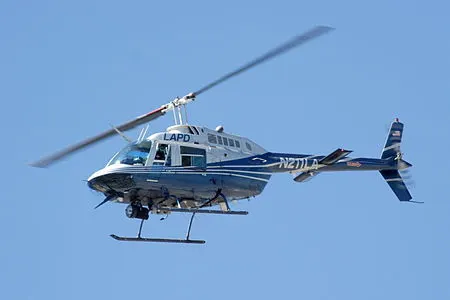
Airbus:
Airbus is a European aviation manufacturer whose headquarters is in Netherlands, but with operations in France, Germany, and Spain. It has been in business since 1970 and specialises in huge planes capable of transporting a large number of people. The maximum take-off weight of and airbus can be high as 575,000 kg.
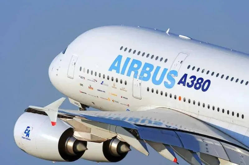
Military Aircraft:
Military aircraft are fixed-wing or rotary-wing aircraft employed by a lawful or insurgent armed force. A noncombatant aircraft, a marine or navy aircraft, or an airforce aircraft could all fall into this category. This could be used for spying, an attack, or transportation. The maximum take-off weight is around 265.3 tonnes.
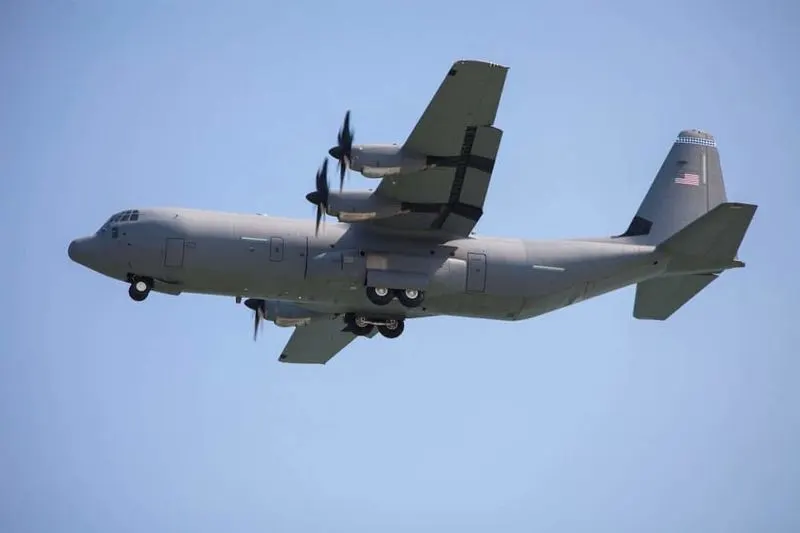
Fighter Jets:
In air-to-air combat, fighter jets' primary mission is to destroy hostile aircraft. It is one of the most commonly utilised combat aircraft types. These are designed for both defensive and offensive operations, such as attacking the adversary or engaging in defensive techniques. Cannons, guided missiles, bombs, machine guns, and rockets are among the weaponry they can transport. The weight of a fighter jet can range from 45,000 lb (20,411 kg) class 81,000 lb (36,700 kg) at max gross takeoff.
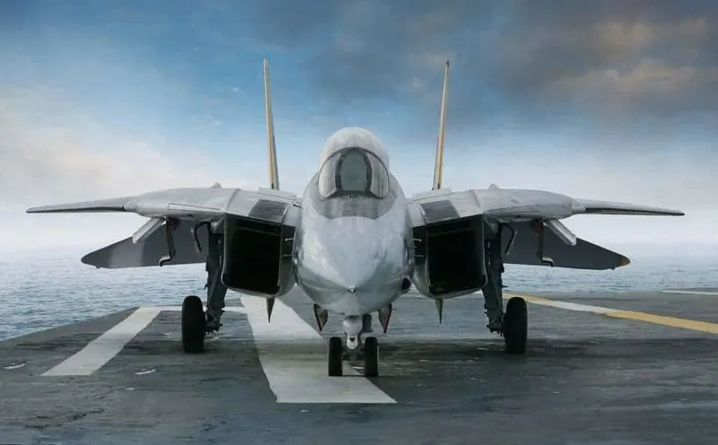
These are some of the basic classification of aircrafts seen considering the weight of the aircrafts.
2)
According to an article from NASA, the Air speed is given by the difference of ground speed and wind speed for an aircraft. Hence we can say that air speed and ground speed aren't the same.
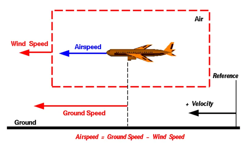
Aerodynamic forces are generated by an object moving through a fluid (liquid or gas). To generate lift, an object must move through the air, or air must move past the object. Aerodynamic lift depends on the square of the velocity between the object and the air. Here not only the object is moving but the air is also moving. It is important to select a fixed reference point and measure velocities relative to the fixed point in order to properly define relative velocity. The reference point is anchored to the ground in this slide, but it may just as easily be assigned to the aeroplane. It's critical to comprehend the links between wind speed, ground speed, and airspeed.
Wind Speed:
The air travels relative to a reference point chosen on the ground at the wind speed. It's important to note that wind speed is a vector quantity with both a magnitude and a direction. The importance of direction cannot be overstated. A wind of 20 mph from the west differs from a wind of 20 mph from the east. All three basic directions are affected by the wind (north-south, east-west, and up-down). Only velocities along the aircraft's flight path are considered in this diagram. The direction of the aircraft's motion is defined as positive velocity. Cross winds, which are perpendicular to the flight path but parallel to the ground, as well as updrafts and downdrafts, which are perpendicular to the ground, are overlooked.
Ground Speed:
The aeroplane moves relative to a reference point on the ground at ground speed for a reference point chosen on the ground. Because ground speed is also a vector quantity, a comparison of ground speed to wind speed must be made using vector comparison criteria.
Air Speed:
The airspeed, or relative velocity between the object and the air, is a key parameter in the formation of lift. Airspeed cannot be determined directly from a ground position; instead, it must be calculated using the ground speed and wind speed. The vector difference between the ground speed and the wind speed is known as air speed.
Air Speed = Ground Speed - Wind Speed
The airspeed is equivalent to the ground speed on a completely motionless day. The airspeed will be smaller than the ground speed if the wind is blowing in the same direction as the airplane.
3)
An aircraft can move on the airport ground with the engine power but it is not recommended to do so. A towing truck is used to move the aircraft around the airport ground.
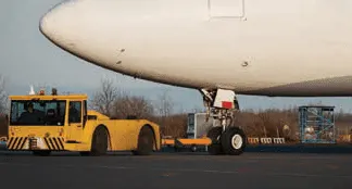
- This is primarily because, the pilots vision to the ground is limited and it is not safe. Hence a towing truck is attached for better vision of the ground.
- Another reason is, aircraft engine are complex mechanical systems which produces high power and noise while running. Hence the engine pulls away any particles that comes across which may cause damage to the engine and limits the safety of the workers.
- These engine causes large noise, which may cause disturbance to the airport workers as well as passengers on-board. And particles from ground have a high chance of getting stuck in the engine causing damage and fuming.
- If in any case the pilot losses control of the engine, it may hit any of the other parked planes or other infrastructures inside.
Because of these following reasons, it is not viable to use engine power for the aircraft to move around inside the airport ground.
4)
Movement of large aircrafts around the airport, to the hanger and along the flight line is achieved by using a tow tractor. this process is known as towing.
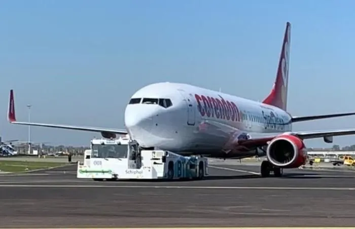
Towing is necessory to enable the aircraft to be moved without engine power. Once the person in charge on the flight deck of the aircraft has given their confirmation of ‘brakes released’ to the person in charge of the ground crew vehicle who are to carry out the tow, the ground crew become responsible for the safe manoeuvring of the aircraft. Formerly, almost all aircraft types required that the ground locking pin be installed in at least the nose landing gear during any towing operation but this is no longer always the case. If a gear ground lock pin is installed for the tow, it may need to be removed after the completion of the manoeuvre. The responsibilities of a ground crew team carrying out an aircraft tow include ensuring that no part of the aircraft structure will impact any fixed object, vehicle, or other aircraft.
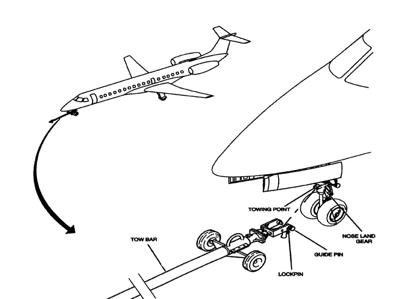
Towing aircraft can be a hazardous operation, causing damage to the aircraft and injury to personnel, if done recklessly or carelessly. This article outline the general procedure for towing aircraft. However, specific instructions for each model of aircraft are detailed in the manufacturer’s maintenance instructions and are to be followed in all instances. When towing the aircraft, the towing vehicle speed must be reasonable, and all persons involved in the operation must be alert. When the aircraft is stopped, do not rely upon the brakes of the towing vehicle alone to stop the aircraft. The person in the flight deck must coordinate the use of the aircraft brakes with those of the towing vehicle. The attachment of the tow bar varies on different types of aircraft. Aircraft equipped with tail wheels are generally towed forward by attaching the tow bar to the main landing gear. In most cases, it is permissible to tow the aircraft in reverse by attaching the tow bar to the tail wheel axle.
5)
Take-off Power:
On take-off, in order to position the aircraft to a safe height away from terrain and obstacles (i.e. a flight path of maximum height and minimum ground distance desired), the engine thrust is set to a high ‘take-off power’ setting (although this is not necessarily full power) and the aircraft attitude is pitched up to maintain a specific speed. Once the ‘safe height’ is reached the engine thrust can therefore be reduced to a more appropriate (i.e. efficient) setting and the aircraft flight path can be changed to a more appropriate (i.e. efficient) flight path. During takeoff, light aircraft typically use maximum power. Large transport category (airliner) aircraft may use less than full power for takeoff to extend engine life, lower maintenance costs, and reduce noise emissions. In some emergency situations, the aircraft's performance can be improved by increasing the power used.
The take-off performance can be predicted using a simple measure of the acceleration of the aircraft along the runway based on force equilibrium.
The forces involved can be classified as Thrust (T), force acting such that pushing the aircraft along the runway. Drag(D) aerodynamic drag resisting the aircraft motion and Rolling resisitance friction (F) due to contact of wheels on the ground.
During take-off imbalance between these forces produce an acceleration along the runway:
dv/dt = (T - D - F) / m , Where m is the mass of the aircraft.
Tyre Design:
Tyres are one of the most critical components of an aeroplane when it comes to safety. They lessen the impact of landing by absorbing the shock. It also provides the essential traction for an aircraft's braking and stopping. During landing, takeoff, taxing, and parking, an aircraft tyre is intended to resist exceptionally severe loads. The number of wheels necessary for an aircraft increases as the aircraft's weight grows, as the weight must be distributed more equally. A Boeing 737NG & 737MAX uses 6 wheels, Boeing 787 uses 10 wheels, Boeing 777 uses 14 wheels and Airbus A380 uses 22 wheels.The tyre is made up of carcass plies. Casing plies is another name for them. The objective of an aircraft tyre is to serve the purposes such as:
- They support an aircraft's weight when it is on the ground.
- It also gives an aeroplane the necessary traction for braking and stopping.
- Tyres also aid to ease the roughness of takeoff, rollout, and taxi operations by absorbing the shock of landing.
Type, ply rating, whether they are tube-type or tubeless, and whether they are bias ply tyres or radials are all used to classify aircraft tyres. It's also possible to identify a tyre by its dimensions. The following is a breakdown of each of these classifications:
A common classification of aircraft tires is by type as classified by the United States Tire and Rim Association. While there are nine types of tires, only Types I, III, VII, and VIII, also known as a Three-Part Nomenclature tires, are still in production.
Although Type I tyres are still made, its design is no longer in use. They are only identified by their nominal overall diameter in inches and are used on fixed-wing aircraft. These tyres have a smooth profile and are no longer used in the modern aviation fleet. They're common in older planes. Type III tyres are widely used in general aviation. They're usually found on small planes with landing speeds of less than 160 miles per hour (mph). Type III tyres feature tiny rim diameters compared to the full width of the tyre and are low-pressure tyres. They have a rather broad footprint and are designed to cushion and offer float. A two-number system is used to identify Type III tyres.
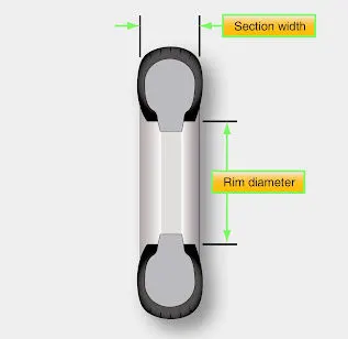
Jet aircraft use Type VII tyres, which are high-performance tyres. They have a great load carrying capacity and are inflated to a high pressure. Type VII tyres typically have a narrower section width than Type III tyres. A two-number system is used to identify Type VII aircraft tyres. Between the two numerals, an X is utilised. The tire's nominal overall diameter is designated by the first number. The breadth of the segment is indicated by the second number. Three-part nomenclature tyres are another name for Type VIII aeroplane tyres. They are employed on high-performance jet aircraft and are inflated to extremely high pressures. The average Type VIII tyre has a low profile and is capable of handling extremely high speeds and weights. It's the most cutting-edge design of all the tyre varieties. The three-part nomenclature is a hybrid of Type III and Type VII nomenclature, based on the overall tyre diameter, section width, and rim diameter. In the designator, the X and "–" symbols are used in the same positions.
Ply rating:
Tire plies are fabric layers enclosed in rubber that are put into the tyre to give reinforcement. The amount of plies utilised in early tyres was proportional to the load the tyre could handle. The number of plies used in aeroplane tyres has become less important as tyre fabrication techniques have improved and contemporary materials have been used. When determining the tire's strength. A ply rating, on the other hand, is used to communicate the relative strength of an aviation tyre. Regardless of the amount of plies used in its production, a tyre with a high ply rating has high strength and can carry heavy weights.
Tube and Tube-less:
Aircraft tyres can be tube-type or tubeless, as previously indicated. This is a common method of tyre classification. Tires meant to be used without a tube feature an inner liner that is specifically engineered to keep air. Tube-type tyres do not have an inner lining since the tube prevents air from leaking out. The word tubeless is printed on the sidewall of tyres that are designed to be operated without a tube. If this identification is missing, the tyre will need to be tubed.
Bias ply or Radial:
The direction of the plies used in the tire's manufacture, either bias or radial, is another way to classify an aviation tyre. Bias ply tyres are the most common type of aeroplane tyre. To make the tyre and give it strength, the plies are wrapped. The angle of the plies in reference to the tire's rotational direction ranges from 30 to 60 degrees. The bias of the fabric from which the plies are made faces the direction of rotation and across the tyre in this manner. As a result, they're known as bias tyres. As a result of the fabric plies being laid on the bias, the sidewall can flex.
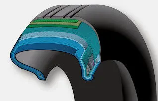
Radial tyres are used on several modern aircraft tyres. Radial tyres have plies that are arranged at a 90° angle to the tire's rotational direction. The non-stretchable fibre of the plies is aligned perpendicular to the sidewall and rotation direction in this design. This gives the tyre more strength, allowing it to carry heavier weights with less deformation.
Carcass plies:
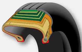
The tyre is made up of carcass plies, or casing plies as they are also known. Each ply is made up of two layers of rubber sandwiched between two layers of fabric, commonly nylon. Plies are put in layers to give the tyre strength and to construct the tire's carcass body. The ply turn-ups are formed by wrapping the ends of each ply around the bead on both sides of the tyre. As previously stated, the angle of the fibre in the ply is adjusted to create a bias or radial tyre. Radial tyres often require fewer plies than bias tyres.
Rolling Resistance:
The force that resists the motion of a body rolling on a surface is called the rolling resistance or the rolling friction given by the equation:
Frr = μrr × mg
Where μrr is the rolling resistance coefficient ,m is the total mass of the aircraft and g is the acceleration due to gravity.
The coefficient of rolling resistance depends on many factors such as tyre pressure, tyre temperature, material of the tyre, thread pattern of tyre and roughness of the road and liquids on the road.
Tyre pressure:
An aviation tyre, often known as a tyre, is made to bear exceptionally severe loads for brief periods of time. The number of tyres necessary for aircraft grows as the aircraft's weight increases, as the weight must be distributed more equally. Fusible plugs (assembled on the inside of the wheels) are also included in aircraft tyres and are designed to melt at a specific temperature. When maximal braking is used during an aborted takeoff or an emergency landing, tyres frequently overheat. The fuses enable a safer failure mode by deflating tyres in a controlled manner, preventing tyre explosions and reducing damage to aircraft and items in the surrounding environment.
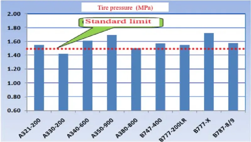
Aircraft tires are subject to huge temperature variations, have much higher pressures, and have much narrower tolerances on what is and isn't acceptable wear. You probably knew that. But how about this: aircraft tires are subject to very large swings in the amount of weight they must support and the resulting amount of sidewall flex can result in damage inside the tire that you cannot see from the outside and can result in a catastrophic tire explosion during takeoff and landing. "Low tyre pressure" means something higher than what you need in the tire. We typically crank it up to between 300 and 400 psi. Dry nitrogen is important because you don't want any condensation inside the tire. But, more importantly, it has to be nitrogen and not air. Air is 78% nitrogen, 21% oxygen, and 1% other stuff. The oxygen is what you have to worry about when using ambient air in tires. Air is more sensitive to temperature changes and the normal heating caused by taxi, takeoff, and landing will cause air to increase in pressure to a much greater extent than pure nitrogen. Air is also more flammable and more likely to "bleed" through rubber. The normal tyre pressure depends on the weight of the plane and number of tires it has, but generally the cold pressure is between 200 and 300+ psi.
Break forces when landing:
Electric Brakes:
The 787 Dreamliner's brake mechanism is controlled by the pilots squeezing the tops of the rudder pedals under their feet and demanding the desired braking rate. This transmits an electronic signal to the Control Units for the Left and Right Brake Systems (BSCUs). The four Electronic Brake Actuator Controllers (EBAC) receive the signals and control the rate of braking on the wheels. Electric Brake Actuators (EBA) are a type of piston that press against the carbon brake discs on each wheel. The second part of the disks are the stators. These sit around each rotor and are fixed in place and thus don’t move. As the wheel turns, the rotors spin round inside the stators.
Anti-skid protection:
When landing on slick runways, it's possible that the wheels will begin to skid as the brakes are applied. Each wheel includes anti-skid protection to prevent this from happening and to preserve maximum effective braking. The brake units know how fast the wheels should be spinning because they use a variety of sources to estimate the aircraft speed. If the wheel's speed reduces dramatically, it's because the brake pressure on that wheel is too high, and the wheel is just skidding on the surface.
Autobrake:
To help us get the braking underway as soon as we touch down, we have the autobrake system.This provides automatic braking at a preselected rate as soon as the aircraft senses that it is on the ground. It also provides full braking pressure in the case of a rejected takeoff if the speed is above 85 knots (98 mph).
Parking brake:
Every now and then, we must apply the brakes and keep them applied. This comes in handy on long taxi rides to the runway and, of course, when parked at the gate. By fully pushing both toe brakes and drawing the parking brake lever up, the park brake is activated. We can then let off of the pedal pressure with this set. Simply press the brake pedals again to disengage.
PART B:
6)
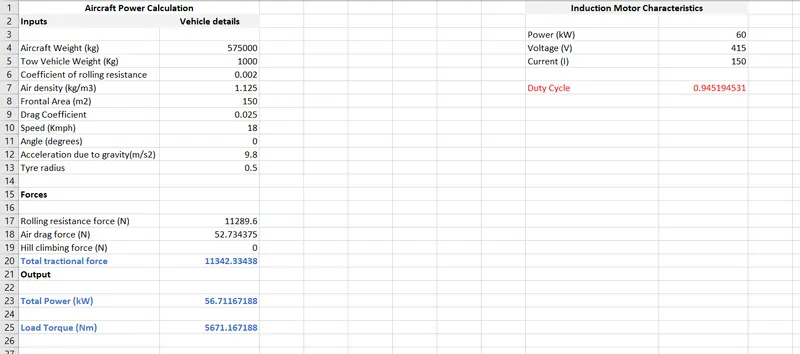
A)Here we are considering Airbus A320 aircraft. Our objective is to find the force and power required by the towing vehicle inorder to push/pull the aircraft. First we need to define some values inorder to find the forces:
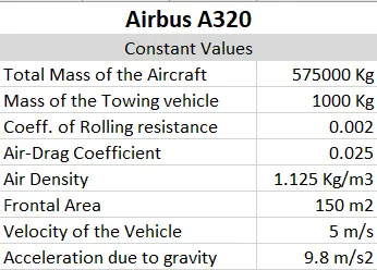
From the above data to calculate the overall forces acting on the aircraft:
Rolling Resistance force:
Rolling resistance force of aircraft is given by:
Frr1 = μrr × mg = 0.002×575000×9.8 = 11.27 kN
Rolling resistance force of towing vehicle is given by:
Frr2 = μrr × mg = 0.002×1000×9.8 = 19.6 N
Total Rolling resistance force = Frr1+Frr2 = 11.29 kN
Aerodynamic Resistance force:
Fad = 0.5 × ρ × A × V^2 × Cd
where ρ is the air density, V is the velocity, A is the frontal area and Cd is the air drag coefficient.
Fad = 0.5 × 1.125 × 150 × 25 ×0.025 = 52.73 N
'It is to be seen that since the tow vehicle is moving with the aircraft in plain ground Hill-Climbing force will not be considered'.
Therefore,
Total Reaction Force = Rolling Resistance force + Aerodynamic Resistance force = 11.34 kN
Now to calculate the power required by the tow vehicle to push/pull is given by:
P = F × V = 11.34 × 5 = 56.7 kW.
Hence, the power required by the tow vehicle to push/pull will be 56.7 kW.
B) The simulink model of the above mentioned problem can be obtained as:
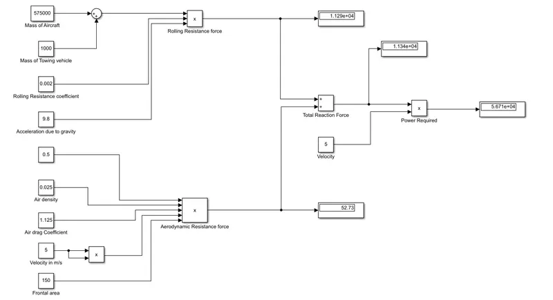
The simulink model shows the final power required as 56.71 kW in the display block.
7)
From the previous question, power required by the tow vehicle is shown as 56.71 kW and Reactional force = 11.34 kN.
Assumed Parameters:
| Aircraft mass | 575000 Kg |
| Towing vehicle mass | 1000 Kg |
| Coeff of Rolliing Resistance | 0.002 |
| Air density | 1.125 kg/m3 |
| Air drag coeff | 0.025 |
| Frontal Area | 150 m2 |
| Tyre pressure | 203 PSI/14 bar |
| Towing velocity | 5 m/s |
| Towing time | 3 min |
| Radius of towing vehicle wheel | 0.5m |
From the above model the calculated traction force is 11.34 kN. (From previous question)
And Power required by the tow vehicle is 56.71 kW. (From previous question)
Torque required = F × Wheel radius = 11340 × 0.5 = 5670 Nm
Required Energy for towing application = P × time = 56.71 × 3/60 = 2.83 kWh
Assuming an induction motor with rating of 60 kW, 415V, 150A with 94% efficiency.
Therefore, Duty cycle = Output power/ input power = 56.71/60 = 0.94.
Hence the Duty Cycle ranges from 0 to 0.94.
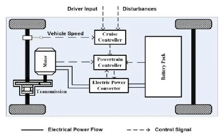
BLOCK DIAGRAM REPRESENTATION:
MODEL:
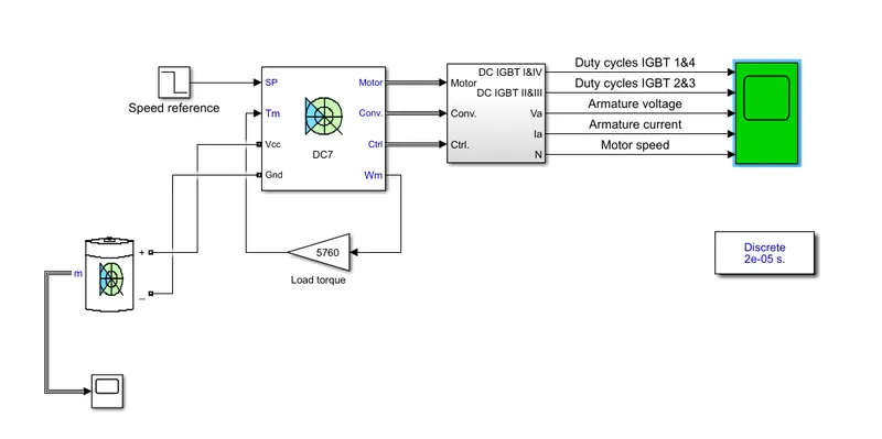
By changing the load torque to desired value the simulation results where obtained.
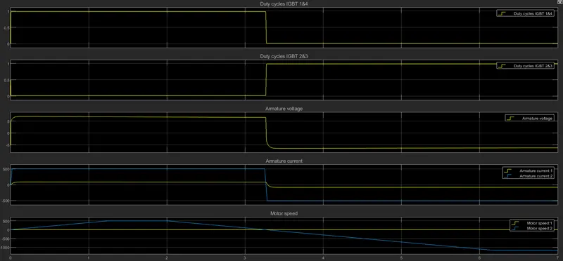
Here, the first regulator is a speed regulator, followed by a current regulator. The speed regulator outputs the armature current reference (in p.u.) used by the current controller in order to obtain the electromagnetic torque needed to reach the desired speed. The speed reference change rate follows acceleration and deceleration ramps in order to avoid sudden reference changes that could cause armature over-current and destabilize the system. The current regulator controls the armature current by computing the appropriate duty ratios of the 5 kHz pulses of the four IGBT devices (Pulse Width Modulation). For proper system behaviour, the instantaneous pulse values of IGBT devices 1 and 4 are opposite to those of IGBT devices 2 and 3. This generates the average armature voltage needed to obtain the desired armature current. In order to limit the amplitude of the current oscillations, a smoothing inductance is placed in series with the armature circuit.
B) EXCEL SHEET PARAMETERS