Week-7 Challenge: DC Motor Control
Ans 1A)
Explanation:
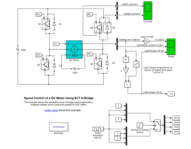
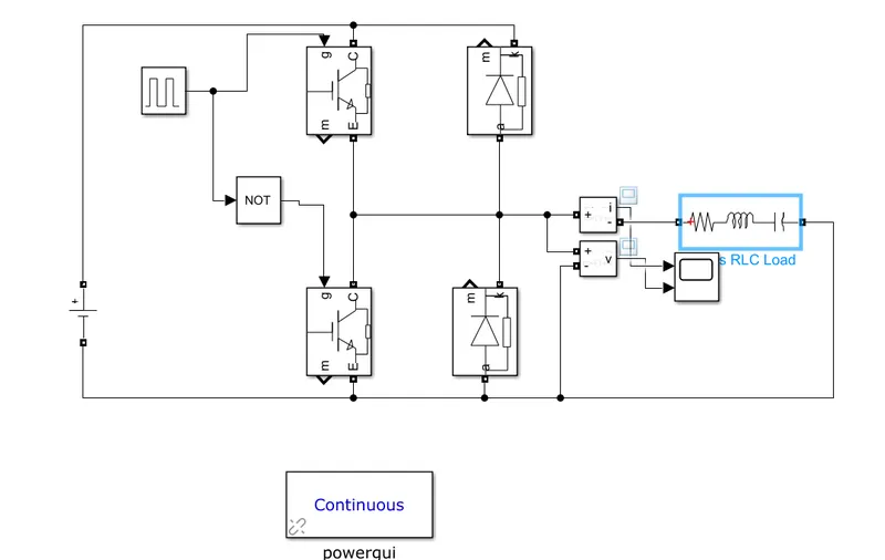
The above diagram shows the Four Quadrant Chopper.
Dc Motor is controlled with the help of four quadrant chopper.
Pulse are genreated with refers to motor speed.
When Q1 and Q4 are fired, a positive voltage is applied to the motor and diodes D2-D3 operate as free-wheeling diodes when Q1 and Q4 are switched off.
When Q2 and Q3 are fired, a negative voltage is applied to the motor and diodes D1-D4 operate as free-wheeling diodes when Q2 and Q3 are switched off.
1B)
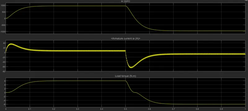
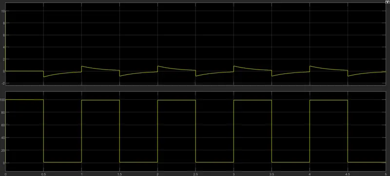
Reason for Armature current shoot is because of sudden change in switching condiotion.
Intially the motor starts in the positive direction . At t= 0.5 sec., the armature voltage is suddenly reversed and the motor runs in the negative direction with Spike.
Ans 1C:
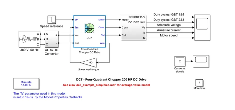
DC-7 Block:
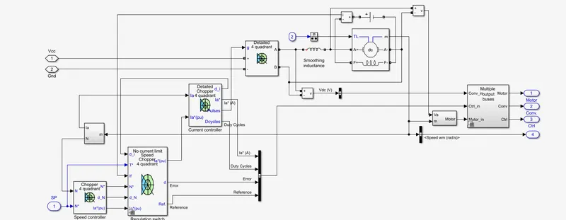
The first regulator is a speed regulator, followed by a current regulator.
The speed regulator outputs the armature current reference (in p.u.) used by the current controller in order to obtain the electromagnetic torque needed to reach the desired speed.
The speed reference change rate follows acceleration and deceleration ramps in order to avoid sudden reference changes that could cause armature over-current and destabilize the system.
The current regulator controls the armature current .For proper system behaviour, the instantaneous pulse values of IGBT devices 1 and 4 are opposite to those of IGBT devices 2 and 3.
This generates the average armature voltage needed to obtain the desired armature current.
In order to limit the amplitude of the current oscillations, a smoothing inductance is placed in series with the armature circuit.
Ans 2:
Simulink model
Output Wave form:
Ans 3:
Working Principle and Operation of BLDC Motor
BLDC motor works on the principle similar to that of a conventional DC motor, i.e., the Lorentz force law which states that whenever a current carrying conductor placed in a magnetic field it experiences a force. As a consequence of reaction force, the magnet will experience an equal and opposite force. In case BLDC motor, the current carrying conductor is stationary while the permanent magnet moves.
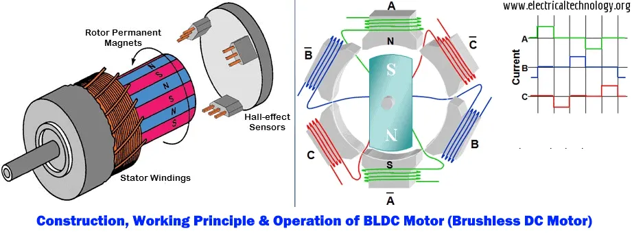
When the stator coils are electrically switched by a supply source, it becomes electromagnet and starts producing the uniform field in the air gap. Though the source of supply is DC, switching makes to generate an AC voltage waveform with trapezoidal shape. Due to the force of interaction between electromagnet stator and permanent magnet rotor, the rotor continues to rotate.
Consider the figure below in which motor stator is excited based on different switching states. With the switching of windings as High and Low signals, corresponding winding energized as North and South poles. The permanent magnet rotor with North and South poles align with stator poles causing motor to rotate.
Observe that motor produces torque because of the development of attraction forces (when North-South or South-North alignment) and repulsion forces (when North-North or South-South alignment). By this way motor moves in a clockwise direction.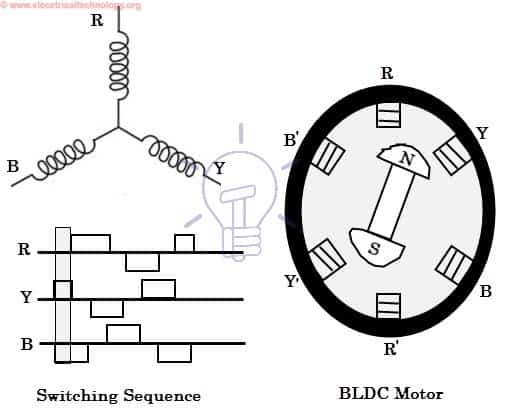
Here, one might get a question that how we know which stator coil should be energized and when to do. This is because; the motor continuous rotation depends on the switching sequence around the coils. As discussed above that Hall sensors give shaft position feedback to the electronic controller unit.
Based on this signal from sensor, the controller decides particular coils to energize. Hall-effect sensors generate Low and High level signals whenever rotor poles pass near to it. These signals determine the position of the shaft.
Brushless DC Motor Drive
As described above that the electronic controller circuit energizes appropriate motor winding by turning transistor or other solid state switches to rotate the motor continuously. The figure below shows the simple BLDC motor drive circuit which consists of MOSFET bridge (also called as inverter bridge), electronic controller, hall effect sensor and BLDC motor.
Here, Hall-effect sensors are used for position and speed feedback. The electronic controller can be a microcontroller unit or microprocessor or DSP processor or FPGA unit or any other controller. This controller receives these signals, processes them and sends the control signals to the MOSFET driver circuit.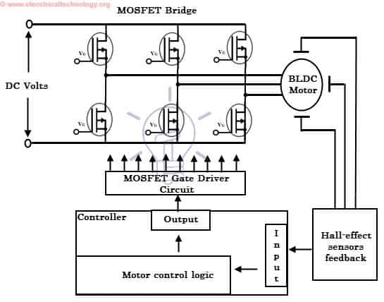
In addition to the switching for a rated speed of the motor, additional electronic circuitry changes the motor speed based on required application. These speed control units are generally implemented with PID controllers to have precise control. It is also possible to produce four-quadrant operation from the motor whilst maintaining good efficiency throughout the speed variations using modern drives.