Week-7 Challenge: DC Motor Control
1).A) Explaination of MATLAB demo model named 'Speed Control of DC motor using BJT H-bridge:
The block diagram of given model designed in the simulink is as shown in the following figure.
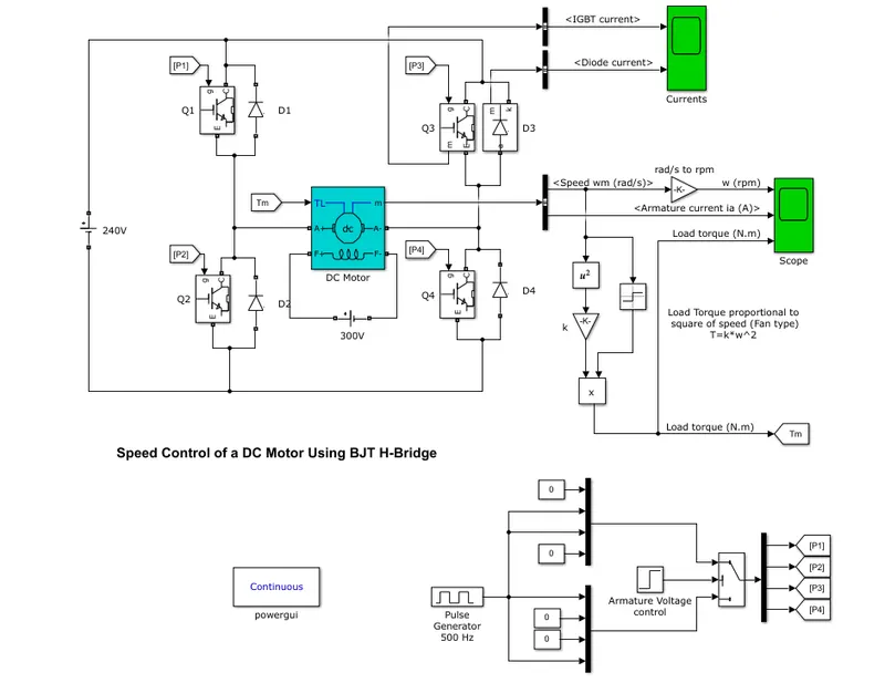
- Here, motor employed is conventional DC motor (brushed type), so its input supply should be of DC only(240V DC is taken as source voltage because motor parameters are 240V DC, 5HP,1750rpm, Field:300V, so field winding is excited by the 300VDC supply.
- Inorder to control the speed of the motor, H-bridge comprising of BJTs (4 Quadrant chopper) is used which generates variable DC voltage which results in variation of speed of the motor.
`:'NpropE_b` Because `E_b = (phiZNP)/(60A)`
`Nprop(V-I_a**R_a)`
where N is the speed of the motor in rpm
`E_b` is the back emf of the motor in volts
V is the input voltage to the motor in volts
`I_a`is the armature current of the motor in amperes
`R_a`is the resistance of the motor in ohms
- Load torque is applied to the motor which is proportional to square of its angular speed (similar to fan load).
`T_Lpropomega_m^2`
`T_L=k*omega_m^2`
- The Bipolar Junction Transistor (BJT) when used for power switching applications, operates as an IGBT. When it is conducting (BJT operating in the saturated region), a forward voltage Vf is developed between collector and emitter (in the range of 1 V). Therefore, the IGBT block can be used to model the BJT device.
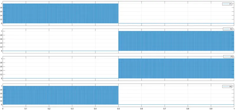
- Here, the control signals are given in such a way that motor runs in forward direction for 0.5seconds and in reverse direction for another 0.5 seconds. So, the total simulation time is set to 1 second.
- For forward motoring, the control signals/pulses (P1 and P4) for Q1 and Q4 are given during first half second and for reverse motoring, the control signals (P2 and P3) are applied to Q2 and Q3 as shown in the following figure.
PULSE GENERATION TECHNIQUE:
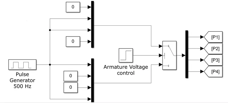
- Here, IGBTs Q1 and Q4 are triggered during first half of simulation time and IGBTs Q2 and Q3 are triggered during second half of simulation time.
- In the above figure, switch is controlled by step signal (named as Armature voltage control). The switch connects through input 1 only when input 2 satisfies the selection criteria otherwise it passes through input 3.
- Here, the selection criteria is defined as magnitude of input 2 greater than or equal to threshold value of the switch.
- Step signal fed as input 2 for the switch starts at 0.5 seconds with an amplitude of 1 unit where the threshold of the switch is defined as 0.5 units.
- From the beginning of the simultaion to the end of first half of simulation time (0 `<`t `<`0.5), the input 2 had not satisfied the criteria (u2 `ge`0.5) so the switch passes through input 3 which is the combined inputs of the lower MUX that are extracted using DEMUX that leads to P1 and P4 gets the pulses only from the output of pulse generator whereas the constant zeroes are applied to P2 and P3.
- From the beginnig of second half of simulation time to the end (0.5 `<` t `<` 1), the input 2 had satisfied the criteria (u2 `ge` 0.5) so the switch passes through input 1 which is the combined inputs of the upper MUX that are extracted using DEMUX that leads to P2 and P3 gets the pulses only from the output of pulse generator whereas the constant zeroes are applied to P1 and P4.
RESULTS:
After simulting the model, the following results are observed.
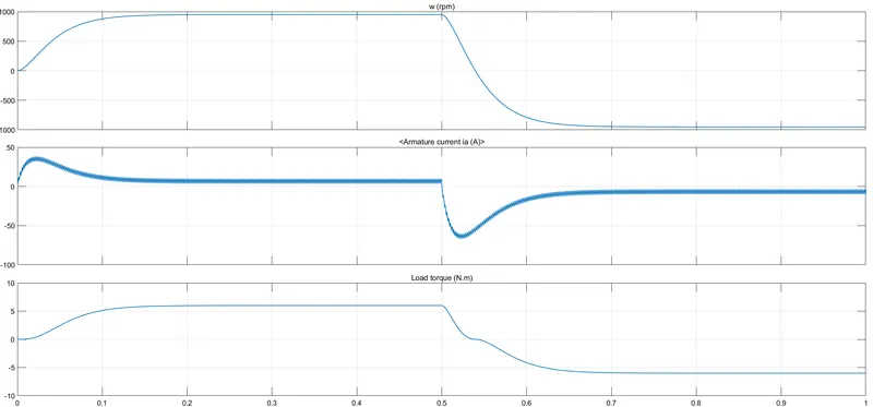
(i) From 0 to 0.5seconds (Forward motoring):
- Control signals/pulses are fed to gate terminals of IGBTs Q1 and Q4, so both those transistors are acting as closed switches that results in application of output voltage of chopper (`V_("in") = D*V_s`) to the input of DC motor with same polarity of the motor.
- So, positive voltage of 180V DC is applied to the motor, that results in production of mechanical power which drives the rotor in forward direction and consequently load torque is applied to the motor.
- Therefore, both speed and torque are positve (speed-torque characteristics in 1st quadrant), this mode is called as forward motoring.
(ii)From 0.5 to 1second (Reverse motoring):
- Control signals/pulses are fed to the gate terminal of IGBTs Q2 and Q3, so both those transistors are acted as closed switches that results in application of controlled voltage to the input of DC motor with opposite polarity of the motor.
- So, negative voltage of 180V DC is applied at input terminals of the motor and current flows in the armature is in negative direction (from A- to A+) that results in rotation of its rotor in reverse direction and now load torque is also applied in reverse direction since 'sign' block detects the sign of the speed and it is applied to load torque value.
- Therefore, both speed and torque are negative (speed-torque characteristics in 3rd quadrant), this mode is called as reverse motoring.
B). Reason for armature current shoot-up:
- Usually, DC motors are started using starters (like 2-point, 3-point and 4-point starters depend on the type of motor) to reduce the starting in rush currents by addition of external resistance and that resistance gradually reduced while rotating the starter consequently the motor pickups the speed.
- Here, no starter is employed and even voltage nearer to rated voltage of DC motor is applied that results in high inrush currents during starting.
- Here, voltage nearer to rated voltage is applied to motor at rest where back emf is zero then armature current passed through the armature winding is given by
`I_a=(V-E_b)/R_a=(V-0)/R_a = V/R_a`
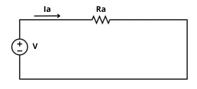
- Here, armature voltage is in hundreds of volts whereas armature resistance is very low around 1 ohm that results in huge armature current shoot up.
- After motor picking up its speed, back emf develops which opposes the input voltage to the motor that results in decrease of current and settles at which load torque is met by the motor torque.
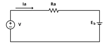
- In reverse motoring mode, the armature voltage polarity gets changed but the back emf changes its polarity only when the rotor starts rotating in the reverse direction. Due to inertia of rotor, motor cannot switch its direction of rotation instantly, so as back emf cannot switch polarity immediately.
`I_a =(-V-E_b)/R_a=-((V+E_b)/R_a)`
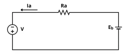
- As the input voltage and back emf are aiding each other, it will results in more current shoot up than in case of starting.
- Later, the back emf reverses its polarity as the rotor rotates in reverse direction as shown in the below picture.
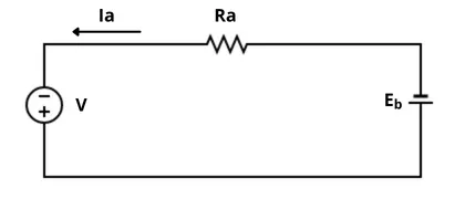
`I_a=-((V-E_b)/R_a)`
Therefore, to eliminate the high inrush currents during starting, the voltage applied to the motor is to be increased slowly by increasing the duty cycle of the chopper is to be gradually.
2).Two-Quadrant chopper using simulink:
The block diagram of 2-quadrant chopper modelled in simulink is shown in the below figure.
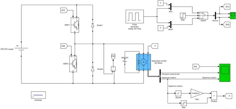
Here, two number of IGBTs and diodes are connected as shown above to develop two quadrant chopper.
The rating of DC motor which is employed as load : 240V DC, 5HP, 1750rpm, Field:300V DC.
Load torque applying on the motor is fan load i.e, `T_Lpropomega^2`
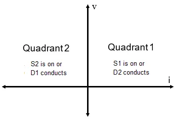
For motoring operation, IGBT 1 is triggered and diode D2 starts conducts when IGBT 1 is turned OFF for freewheeling action.
For braking operation, IGBT 2 is triggered and diode D1 starts conducts when IGBT 2 is turned OFF then current is fed back to the source.
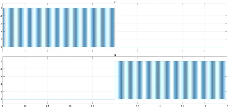
So, for first half of simulation time, IGBT 1 is triggered for motoring operation and for second half of simulation time, IGBT 2 is triggered for braking operation @100Hz, 75% duty cycle as shown in the following picture.
The voltage across the load either source voltage (when IGBT 1 turned ON) or zero (when Diode D2 conducts) and load current is positive during motoring operation and negative during braking operation. So, the motor is operated only in first and second quadrants only.
PULSE GENERATION TECHNIQUE:
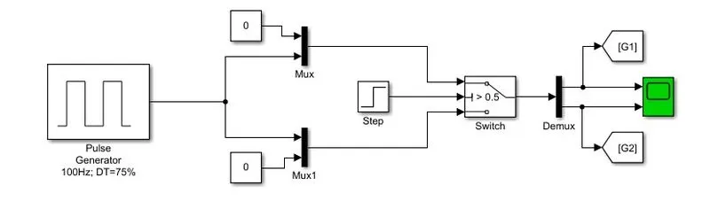
- Here, IGBTs Q1 is triggered during first half of simulation time and IGBTs Q2 is triggered during second half of simulation time.
- In the above figure, switch is controlled by step signal.. The switch connects through input 1 only when input 2 satisfies the selection criteria otherwise it passes through input 3.
- Here, the selection criteria is defined as magnitude of input 2 greater than or equal to threshold value of the switch.
- Step signal fed as input 2 for the switch starts at 1 second with an amplitude of 1 unit where the threshold of the switch is defined as 0.5 units.
- From the beginning of the simultaion to the end of first half of simulation time (0 `<`t `<`1), the input 2 had not satisfied the criteria (u2 `ge`0.5) so the switch passes through input 3 which is the combined inputs of the lower MUX that are extracted using DEMUX that leads to G1 gets the pulses only from the output of pulse generator whereas the constant zero is applied to G2.
- From the beginnig of second half of simulation time to the end (1 `<` t `<` 2), the input 2 had satisfied the criteria (u2 `ge` 0.5) so the switch passes through input 1 which is the combined inputs of the upper MUX that are extracted using DEMUX that leads to G2 gets the pulses only from the output of pulse generator whereas the constant zero is applied to G1.
RESULTS:
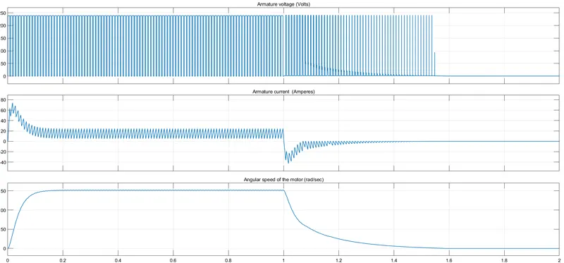
(i) From 0 to 1 second (Forward motoring):
- Here, IGBT 1 is turned ON when it receives its trigger signal, source voltage is applied across the DC motor with correct polarity that results in forward motoring.
- During ON period of IGBT1, the inductance opposes the sudden raise in current, so the current increases linearly and voltage across the motor is equal to the source voltage.
- During the OFF period of IGBT 1 (DT =75%), diode D1 conducts and the energy stored in the inductance of motor free wheels through that diode without change in direction of current due to inductance property, so the current decreases linearly and voltage across the motor is zero as the motor terminals are shorted through diode D2.
- From the plot, we can observe that, motor is rotating with angular speed of around 150 rad/sec.
(ii) From 1 to 2 seconds (Forward braking):
- Here, IGBT 2 is turned ON when its receives its trigger signal, the energy stored in the inductor free wheels through IGBT 2 with negative direction of current flow.
- During OFF period of IGBT 2, the current is fed back to the source through diode D1.
- As the current is negative, the electromagnetic developed by the motor opposes the forward rotation of the rotor.
- From the plot, we can observe that, the speed of the motor is gradually decreased and reaches to zero.
3).OPERATION OF BLDC MOTOR:
CONSTRUCTION:
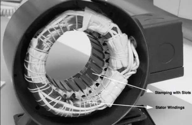
The stator construction of the BLDC motor is similar to that of the induction motor. The stator is composed of many silicon sheets stacked together which have slots that are axially cut to accomodate the stator winding. Usually, the stator winding is connected in star fashion.
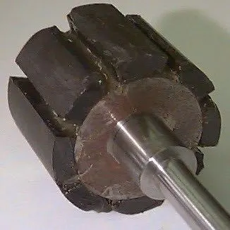
The rotor comprises of permanent magnets (rare earth magnets like Neodymium etc) on its periphery as shown in the below figure. The number of pole pairs on the rotor depend on the application requirement.
WORKING:
- The brushed DC motor works on the principle 'Lorenz force law which states that whenever a current carrying conductor is placed in magnetic field, it experiences a force.' In which permanent or electromagnets are placed on the stator and armature winding is on the rotor. In order to experience unidirectional torque, the direction of the current in the armature coil is to be reversed when that coil is entering into other stator magnetic pole region which is done by commutor that spins along with the rotor.
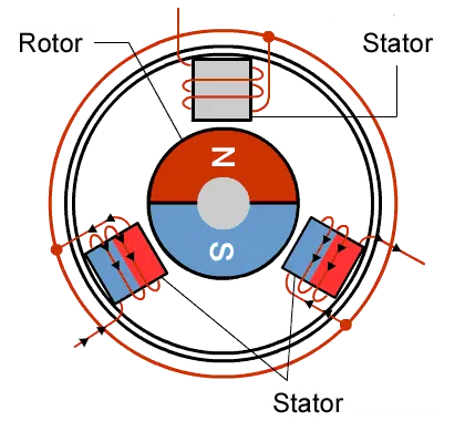
- As shown in the above figure, BLDC motor is in contrast to the brushed DC motor that is permanent magnets are placed on the rotor where as the armature winding is placed on the stator with electronic commutation. But the principle of working of BLDC motor is same as that of brushed DC motor i.e, Lorenz force law.
- Here, armature winding is stationary whereas permanent magnets rotates.
- The stator winding is excited with DC supply which results in production of magnetic field that interacts with the permanent magnet's field that results in production of force on the rotor caused by the force of attraction and repulsion between the stator and rotor poles.
- The direction of current in the armature windings are altered (reversed) after every certain amount of period to produce unidirectional torque on the rotor. The commutating action is carried by the static electronic switch.
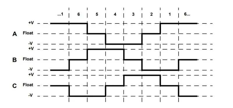
- BLDC motor employs hall sensors which detects the rotor position and sends the signals to the controller which then excites the particular windings with required polarity as shown in the below image.