Week-7 Challenge: DC Motor Control
1. A. Explain a MATLAB demo model named ‘Speed control of a DC motor using BJT H-bridge’.
B. Comment on the armature current shoot-up from the scope results.
C. Refer to the help section of ‘The Four-Quadrant Chopper DC Drive (DC7) block’. Compare it with the H-bridge model.
Solution:
BJT(Bipolar JUnction Transistor): A BJT is a three terminal semiconductor device that consists of 2 p-n junctions which are able to amplify or magnify a signal. It is a current control device. The 3 terminals of the BJT are base, collector and emitter. A signal of small amplitude spplied to the base is available in the amplified form at the collector of the transistor. This is the amplication provided by BJT. It does not require any external source of DC supply to carry out the amplification process. There are 3 operating regions in BJT, they are:
- Active Region: The region in which transistor operates as an amplifier.
- Saturation Region: The region in which the transistor is fully operates as a switch such that collector current is equal to the saturation current.
- Cut off Region: The region in which the transistor is in OFF condition and collector current is zero. Here the transistor acts as an open switch.
BJTs are of 2 types namely NPN & PNP based on doping types of the 3 terminals. Am NPN transistor consists of 2 semiconductor junctions that have a thin p-doped anode region and PNP transistor also consists of 2 semiconductor junctions that have a thin n-doped cathode region. The flow of charge in BJT is due to the diffusion of charge carries between the 2 regions belonging to different charge concenntrations. THe emitter region is highly doped when compared to the other layers. Both collector and base layers have the same charge carrier concentrations. Among these, the base-emitter junction is forward biased and the base-collector junction is reverse biased. The following diagram shows the BJT structure,types,circuit diagram and operating characterstics.
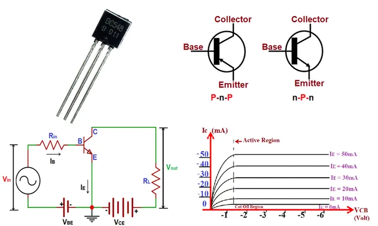
Applications of BJT: We know that BJTs are used as a switch, an amplifier, as a filter and as on oscillator. And they are also used as a detectors or known as demodulators. BJT finds application in clipping circuits so that waves can be saped. And in Logic and Switching circuits aso we can use the BJT.
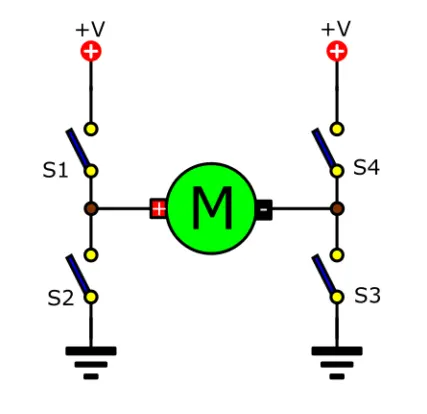
H-Bridge: A H-Bridge is a simple circuit containing 4 switching elements with the load at center in a H-type configuration. That lets us control a DC motor to go backward or forward. A DC motor spins either backward or forward depending on how we connect the +ve and -ve terminals of a motor. Will use it with a Microcontroller such as an Aurdino to control motors. The following diagram shows the simple basic circuit of the H-Bridge.
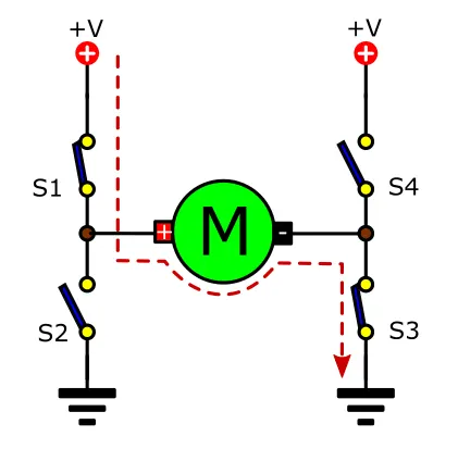
If we cose the switch 1 & 4 , it means the +ve terminal of motor is connected to the left side and -ve terminal to the right side. Then the motor starts running in one direction i.e. in clockwise direction. It causes the current flowing through the positive terminal of the motor. The following figure shows this arrangement.
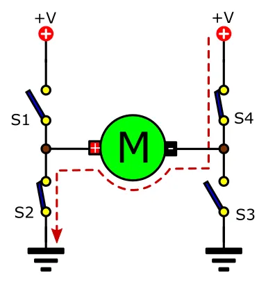
Now if u close the switch 2 & 3 then the +ve terminal is connected to the left side and -ve terminal is connecterd to the left side of the motor. In this case the motor starts running in opposite direction i.e. in Counter clockwise direction or Anti clockwise direction. Here the current will flow through the negative terminal of motor. The following figure shows this phenomenon.
A. Explain a MATLAB demo model named ‘Speed control of a DC motor using BJT H-bridge’.
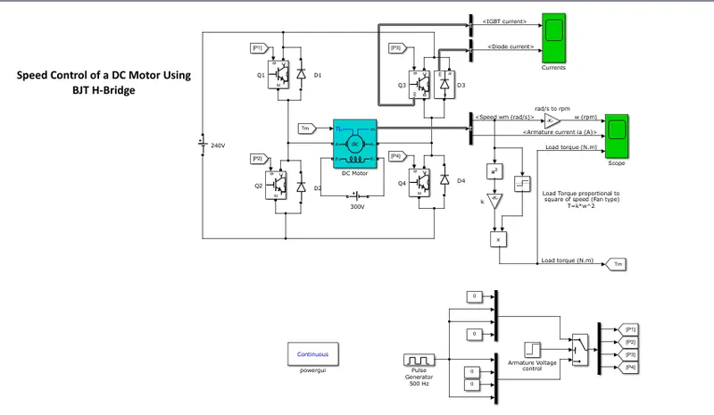
First will open the MATLAB demo model 'Speed control of a DC motor using BJT H-Bridge' from the help documets. When we open the model it appears as shown in the following figure.
Operation:
In this model the switching elements Q1,Q2,Q3,Q4 are usually BJT type but in Power switching applications BJT is opererated as IGBT. The diaodes D1,D2,D3,D4 are called catch diodes and are usually of schottky type. The top end of the bridge is connected to power supply. In general all 4 switching elements can be turned ON and OFF independently through some procedure. If the switches Q1 & Q4 are turned ON the left lead of the motor will be connected to the power supply. Current starts flowing through the motor which energises it in forward direction and motor starts spinning. Simply it is shown through following image. D2 and D3 will acts as free wheeling diodes when Q1 and Q4 are turned OFF.

If Q2 & Q3 are turned ON, then the reverse will happen. The motor energised in the reverse direction and shaft will starts spinning in backward direction. Which is shown through following image. the diodes D1 and D4 are acts as free wheeling diodes when Q2 and Q3 are turned off.

In a bridge we should never ever close both Q1 and Q2 or Q3 and Q4 at the same time. If we did that, a low resistance path is created between power and GND effectively short circuiting the power supply. This condition is called Shoot-through condition. It will quickly damage or destroy the bridge.
Adding diodes across the switches is to protect the electricity that may flow backward from the motor which makes damage to the transistor. When we disable the transistors to stop running the motor the energy needs to be released. If diodes are connected in reverse direction to the transistors then it will give a path for current to release this energy. Without them the voltage rises and damages the transistors.
Details: The IGBT switch is controlled by a simulink signal i.e, 1 or 0. The DC motor uses the preset model which is 5HP, 24V, 1750RPM. It simulates the load as fan type and where the load torque is directly proportinal to V². The armature voltage is varied from 0-240V when duty cycle is varied from 0% to 100%. Duty cycle value is specified in the Pulse Generator block.
B. Comment on the armature current shoot-up from the scope results.
So by running the above model at 75% of duty cycle will see the following results through the scopes provided across different parameters.
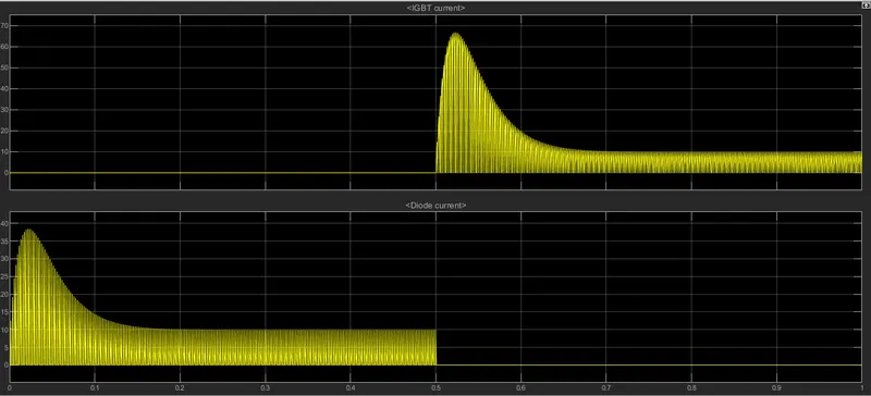
In the above figure we can see that the result plots of IGBT current and diode current across the Q2 and Q3 switches as we provided the scope across them. From the result plots we can observe that before t=0.5sec, the diode currents will come into the picture and after 0.5sec the IGBT current will appears. It is according to the operation as we discussed before. Where Q1 & Q4 are ON for first 0.5sec which is indicated through the Diode current plot and where the IGBT current across Q2 and Q3 is off. When they(Q2 & Q3) are turned ON then the Current across the diodes is off and IGBT current across Q2 & Q3 is come into the picture.
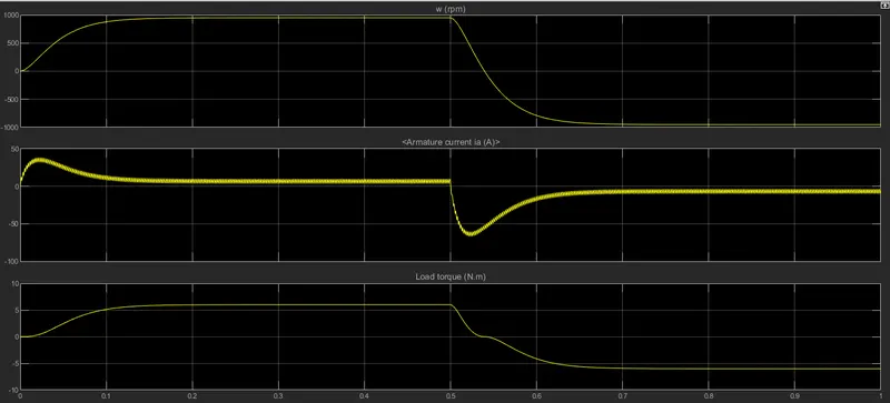
The above plots shows the changes in Speed, Armature current and Load torque.
NOTE: Q1 & Q4 are turned ON from 0-0.5sec(Forward biased condition)(motor runs in positive direction), Q2 & Q3 are Turned on from 0.5-1sec(Reverse biased condition)(motor runs in a negative direction).
When the circuit is in forward biased condition i.e. from 0-0.5sec intially sudden shoot up is occured and armature current starts flowing in a ppositive side when the speed also raised and maintained constant and torque is also in positive action. When it goes into Reverse biased condition i.e. from 0.5-1sec revesre shoot up is occured and armature current starts flowing in negative side accordingly the speed is also decreased and torque also acts in reverse direction.
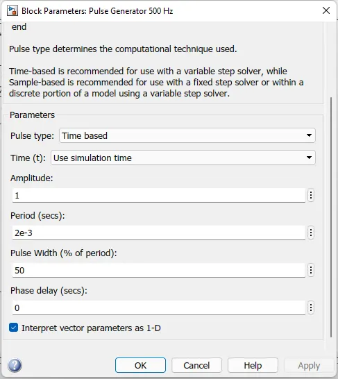
Now to change the shoot up value we are changing the duty cycle from 75% to 50% through pulse generator block. Which is shown in the following image. Accordingle with the duty cycle the values of P1,P2,P3,P4 values are aslo changed which are given across respective switches as shown in the simulink model figure.
So by changing the duty cycle value will obsever the following output plots.
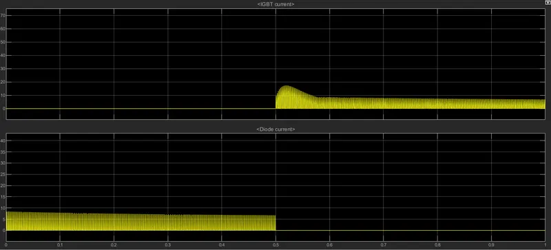
In the above plot it can be observed that sudden shoot up is not acted as 75% duty cycle. Here the shootup is reduced but not completely off. Same as in the previous case the diode current is appears for 0.5sec and thereafter the IGBT current came into picture till then it is OFF.
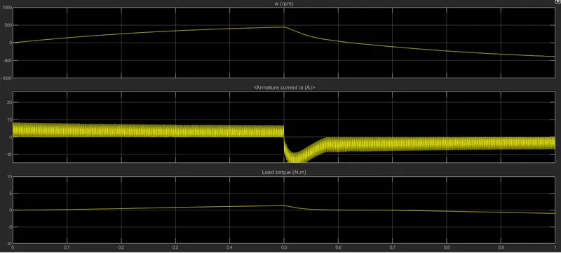
From the above plot we can see the variations of Speed, armature current and Load torque. Where the time period is maintained as same as in the previous case. Here we can observe that there is no starting shoot ups. But if we observe we can see that there is changes in all three parameters across the starting of forward-reverse state ie. at 0.5sec, where the armature currents falls to negative side and maintained a constant value accordingly we can see the same changes in case of speed and load torque also.
So at 50% of duty cycle it can be say that the shoot up is reduced when motor changes its direction from forward to reverse direction, when compared to 75% of duty cycle.
C. Refer to the help section of ‘The Four-Quadrant Chopper DC Drive (DC7) block’. Compare it with the H-bridge model.
Four-Quadrant Chopper DC Drive: Chopper is used for conversion of fixed DC into variable DC. Four quadrant speed control model is designed by using chopper to control the speed of DC motor. This model provides four quadrant speed control of DC motor in both direction i.e. clockwise and anti clockwise direction allong with the braking of the DC motor. This operation will most superior in DC motor than AC because changing the rotation of motor is difficult and complicated in AC compared to DC. In this IGBT is used for speed control of DC motor which is smooth in operation. The chopper circuit designed by IGBT to control the speed of DC motor in both direction. The switching operation of IGBT is done by using PWM(Pulse Width Modulation) technique. As per the variation in the pulses it is easy to control the speed of the motor.
Four quadrant DC motors are extremely used in adjustable speed drive and position control application. Their speeds below base speed can be controlled by armature-voltage control mathod, and above base speed by Field-flux control method. Chopper Dc drive circuit is operated in 4 quadrants i.e. Forward Motoring, Forward Braking, Reverse Motoring and Reverse Braking. This type of chopper is widely used in reversible motor drive. The following figgure shows the circuit diagram of this model.
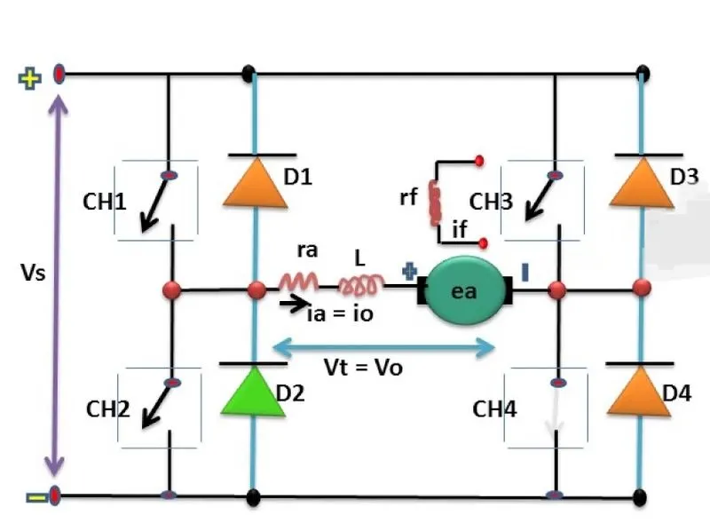
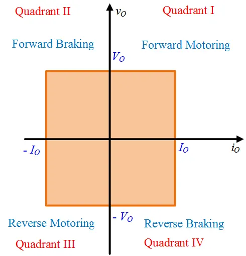
Where CH1,CH2,CH3,CH4 are the choppers and D1,D2,D3,D4 are the diodes connected cross the respective chopper circuit and DC drive is connected as shown in the above figure. The operation of 4 quadrant chopper is shown in the following figure. In the first quadrant, power can be flow from source to load and hence current and voltage in the 1st quadrant are assumed as positive, where the forward motoring action takes place. Similarly in 2nd quadrant operation voltage remains positive but the direction of current is changed to negative, this condition is happened when load is inductive. Where forward braking action is takes place. In 3rd quadrant operation the voltage and current both are in negative but the power is positive, where the Reverse motoring action is takes place. Similarly in 4th quadrant curent is positive and voltage is negative therefore the power is negative. And here Reverse Braking action is takes place.
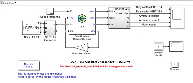
In this model the DC motor of 200HP is seperately excited with a constant 150V DC voltage source. The AC to DC converter is fed by 515V DC bus obtained by rectification of 380V AC 50Hz voltage source. In order to imit this voltage during braking mode, a braking chopper has been added in between the diode rectifier and DC7 block. Where the motor is coupled to a linear load which means that load torque is proportional to the speed. The armature voltage is provided by IGBT is controlled by two PI regulators. For proper behaviour of the system, the instantaneous pulse values of IGBT devices 1 and 4 are opposite to those IGBT devices 2 and 3. This generated the average armature voltage needed to obtain the desired armature current. This arrangement is under the subsystem of the selector block which is shown in the following figure.
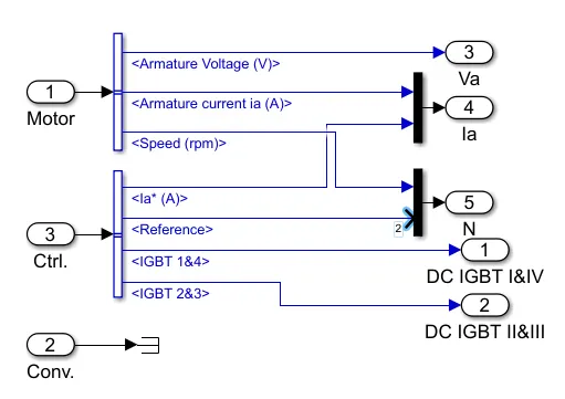
Intially we have to set the bus voltage value at 515V by using GUI block i.e. click on intial states setting button and then Cbus variable. And start the simulation. Here we are taking the time period as t=7sec. BY running the simulation the following result plots are observed from the scope.
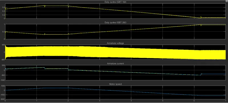
From the above plot we can observe the changes in Motor Armature voltage and current, motor speed and the four IGBT pulses. Where the speed reference is set at 500RPM. we can observe the speed from the speed plot, it is nearly to 450+ RPM and coming to constant around 1.2sec. The armature current plot have small ripples and fast response. At t=3.2sec, the motor speed reches to 0RPM and the load torque reverses and current also flows into negative direction. The pulses of IGBT can be observed that 1 & 4 are opposite to the 2 & 3.
Difference between The Four-Quadrant Chopper DC Drive (DC7) and H-Bridge model:
| The Four-Quadrant Chopper DC Drive (DC7) block | H-Bridge Model |
|
1. This model operates in four modes i.e. Forward Motoring, Forward Braking, Reverse Motoring and Reverse Braking. |
1. This model operates in only 2 modes i.e. Forward Motoring, Reverse Motoring. |
|
2. Regenerative braking is possible with this model. |
2. Regenerative braking is not possible with this model. |
|
3. It has high switching frequency. |
3. Compared to four quadrant chopper model it has low switching frequency. |
|
4.The source is and AC supply which is rectified and taken as DC varrying suply. |
4.The source is fixed DC source. |
|
5.There is no sudden shoot ups in the output plots. |
5.In this model sudden shoot ups are observed. |
|
6. It gives better efficiency compared to H-Bridge model. |
6.The efficiency is low compared to the four quadrant chopper dc drive model. |
2. Develop a 2-quadrant chopper using simulink & explain the working of the same with the relevant results.
Solutions:
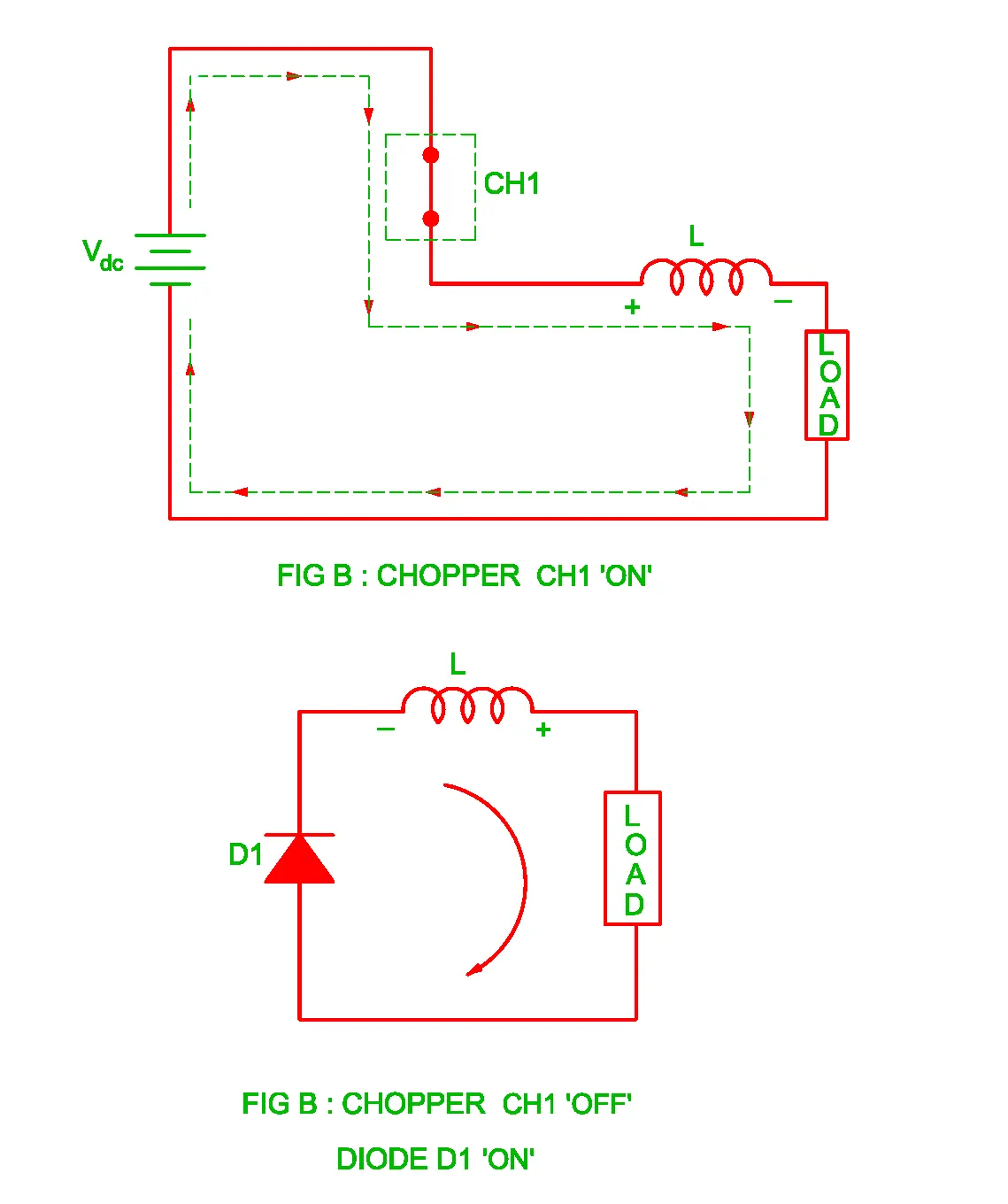
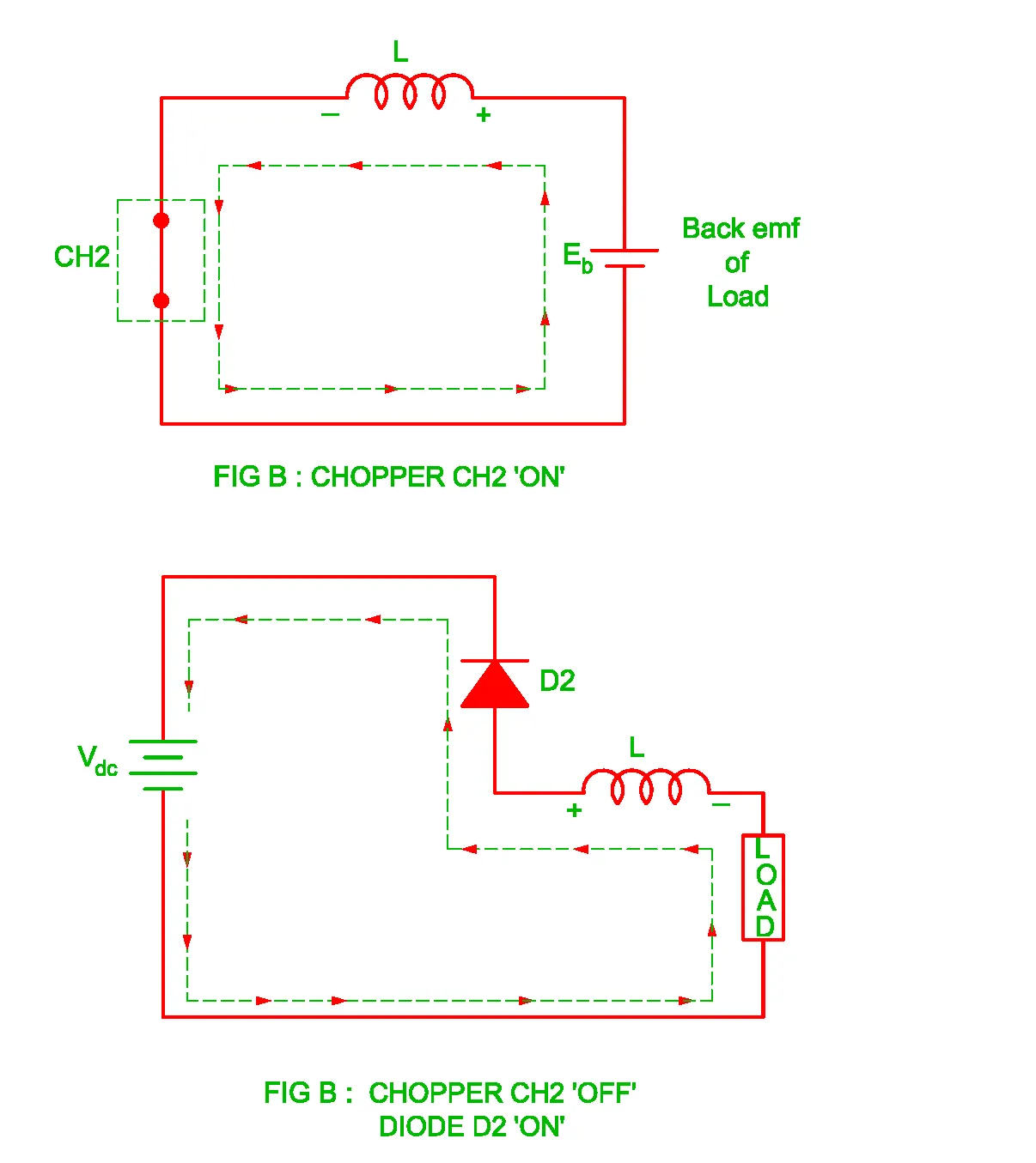
Class C chopper is known as Two quadrant chopper. It is a parallel combination of type A and type B chopper. Which can operate in first as well as in second quadrant. This means that power can either flow from source to load or load to source. To obtain first quadrant operation we should switch ON CH1 and for getting second quadrant operation we should switch ON chopper CH2. It provides a two quadrant operation by retaining the current direction in both motoring and braking modes. The following figure shows the circuit diagram of a Two quadrant chopper and its operation in two quadrants. Where CH1 and CH2 are the choppers working as electronic switches and D1 and D2 are the feedback diodes. Assuming the continuous conduction, both CH1 and CH2 operates simultaneously.
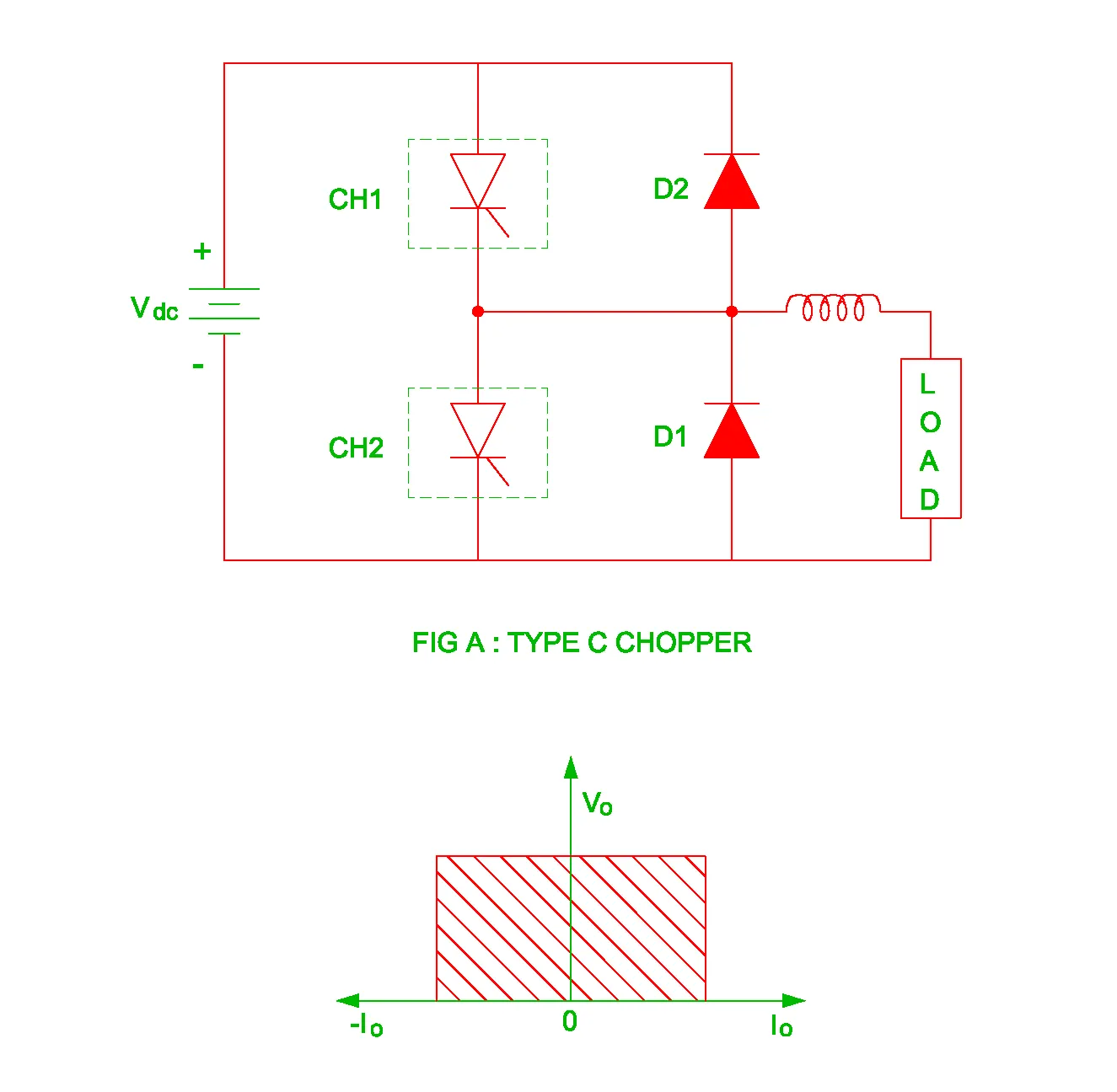
Operation:
When CH1 is switched ON / OFF,
When chopper CH1 is switched ON, source Vs directly gets connected to the load and hence load voltage V0 is equal to source voltage. The direction of load current is from source to load as shown in circuit diagram which is assumed positive.
When CH1 is switched OFF, the diode D1 comes into the circuit as it gets forward biased and hence shorts the load. Therefore, the output voltage Vo becomes zero. However, the Io continuous to die down through D1 and L in the same direction as shown in the following figure. Thus, the average output voltage Vo and Io are positive and hence operation of chopper is in first quadrant.
In this quadrant Vo and Io are positive. So the back emf is positive.
Eb = V-IoRa
where Ra = Armature resistance
Hence motor operates in motoring mode.
When CH2 is switched ON / OFF,
When chopper CH2 is switched ON, load DC source drives current through CH2 and load. The direction of this current Io will be opposite, hence assumed it as negative. Output voltage Vo is zero during this time.
When CH2 is OFF, diode D2 gets forward biased and hence the current into the source from the load. The output voltage V0 in this time as the load is connected to the source through D2 during OFF time of Chopper CH2. Thus, the load current is always negative i.e. operation of chopper is within second quadrant.
In this quadrant Vo is positive and Io is negative. So flux (Φ) is also negative
Eb = Vo+IoRa
Eb>Vo
The motor works as generator and reverse its direction. This happens in Regenerative mode.
The average load voltage is always positive but the average load current may be positive or negative. Therefore, power flow may be from source to load in first quadrant operation or load to source in second quadrant operation
Now coming to our challenge we have developed a two quadrant chopper using simulink as shown in the following figure.
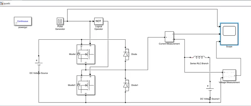
There we have used the following blocks,
MOSFET Block:
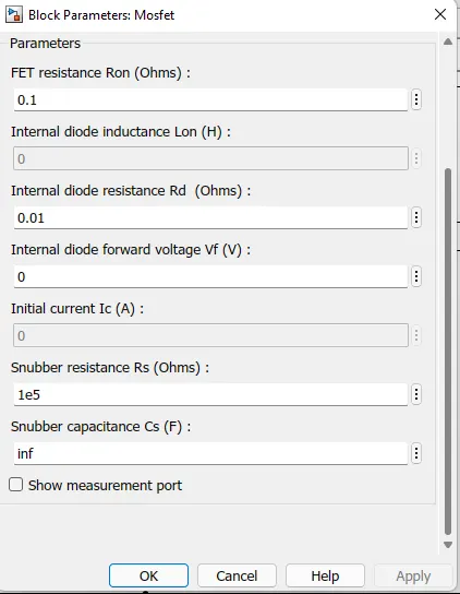
In the MOSFET block we have to uptick the measurement port as shown in the folowing figure.
Diode block: In diode block also we have to uptick the measurement port as same as MOSFET.
Pulse Generator Block:
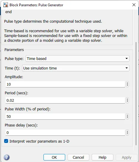
In pulse generator block we have given the Amplitude value as 10, Time period as 0.02sec, and Pulse width as 50%. Pulse width 50% is selected because to operate both the switch half half i.e. 50% On and 50% Off. Which is shown in the following block.
Series RLC Branch:
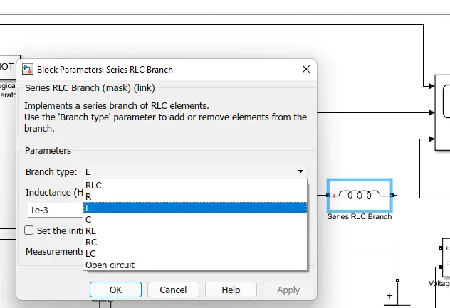
In series RLC block we have select the branch type as L, which is shown in the following figure.
Logicall Operator Block:
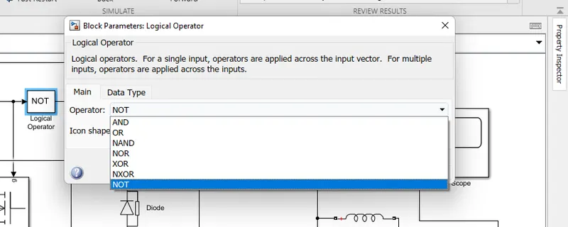
In the logical operator block we have to select NOT gate. We have selected NOT logic operator to ensure that both switches does not conduct simultaneously. In the model we can see that the input of NOT block is connected to upper MOSFET block and output of NOT is connected to lower MOSFET it means that when one is on the other one is off according to the NOT gate operation.
DC Voltage Source:
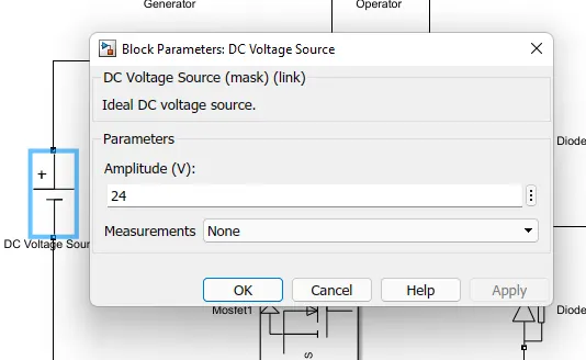
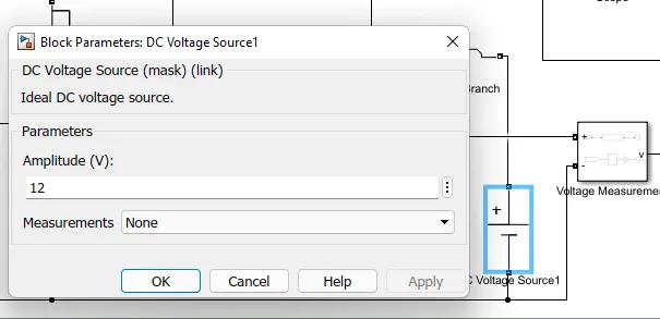
In DC voltage source block we have given the main supply Amplitude(V) as 24V
Load side voltage source Amplitude(V) as 12V.
Current Measurement Block:
From this block we can measure the Current value by connecting it to scope.
Voltage Measurement Block:
From this block we can measure the voltage by connecting it to scope.
Scope Block:
To observe the output plots of current and voltage, input plot of Pulse generator.
Continuous Block:
Without this block we cannot simulate our model continuously.
Simulation Plots:
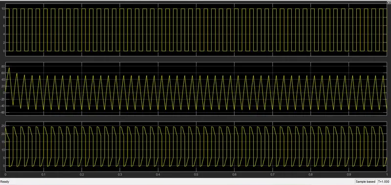
By simulating our model for 1 sec, we can observe the following plots from the scope.
Where the first plot represents the Pulse generator input. Second plot represents the current measurement and third plot represents the voltage measurement.
By zoomin the specified area of the plot we can observe the output clearly.
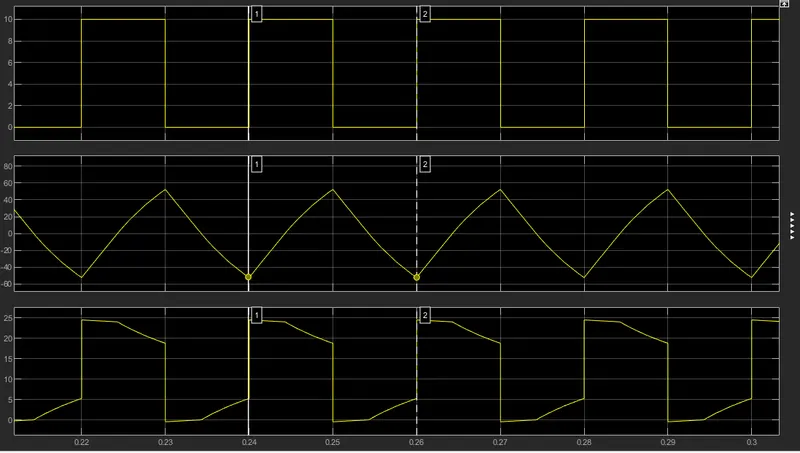
So from the above plot we can observe that at the starting of pulse the current and voltage starts raising to particular range where upper mosfet and lower diode is in conducting mode i.e. in forward biasing mode. And after 0.01 sec upper switch and lower diode stops conducting and lower Mosfet and upper diode starts conducting i.e. in reverse biasing mode. Whre the current starts falling to the negative value and voltage is in positive but there is a fall at the start and only small increase in later. In the first mode Forward motoring action takes place and in the second mode regenerative mode takes place. This has been observed for one pulse of time 0.02sec, the same procedure is happens till 1sec.
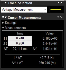
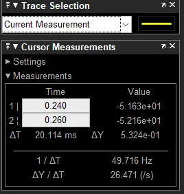
The following blocks are the Traces of voltage and current values measured by using the cursors.
3. Explain in a brief about operation of BLDC motor.
Solution: A Brushless DC electric motor i.e. BLDC motor or BL motor is a synchronous motor using a direct current (DC) electric power supply. It uses an electronic closed loop controller to switch DC currents to the motor windings producing magnetic fields which effectively rotate in space and which the permanents magnet rotor follows. The controller adjusts the phase and amplitude of the DC current pulses to control the speed and torque of the motor. This control system is an alternative to the mechanical commutator used in many conventional electric motors. The following image shows the parts of a BLDC motor.
The construction of a brushless motor system is typically similar to a permanent magnet synchronous motor, but can also be a switched reluctance motor, or an induction motor. The advantages of a brushless motor over brushes motors are high power to weight ratio, high speed, nearly instantaneous control of speed and torque, high efficiency, and low maintainance. Brushless motors find applications in such places as computer peripherals, hand-held power tools, and vehicles ranging from model aircraft to automobiles. In modern washing machines, brushless DC motors have allowed replacement of rubber belts and gearboxes by a direct-drive design. In brushes motors, there are permanent magnets on the outside and a spinning armature which contains electromagnet is inside. There electromagnets create a magnetic field in the armature when the power is switched on and help to rotate the armature. The brushes change the polarity of the pole to keep the rotation on of the armature. The basic working principle for the brushes DC motor and for Brushless DC motor are same i.e. internal shaft position feedback. Brushless DC motor has only two basic parts: rotor and stator. The rotor is the rotating part and has rotor magnets whereas stator is the stationary part and contains stator windings. In BLDC permanent magnets are attached in the rotor and move the electromagnets to the stator. The high power transistors are used to activate electromagnets for the shaft turns. The controller performs power distribution by using a solid-state circuit. Basically, BLDC are of two types, one is outer rotor motor and other is inner rotor motor. The basic difference between the two is only in designing, their working principles are same.
Inner Rotor Design: In an inner rotor design, the rotor is located in the centre of the motor and the stator winding surround the rotor is located in the core, rotor magnets do not insulate heat inside and heat get dissipated easily. Due to this reason, inner rotor designed motor produces a large amount of torque and validly used.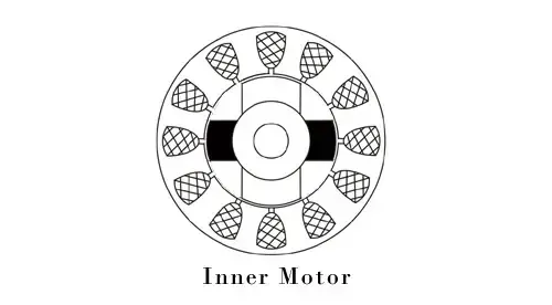
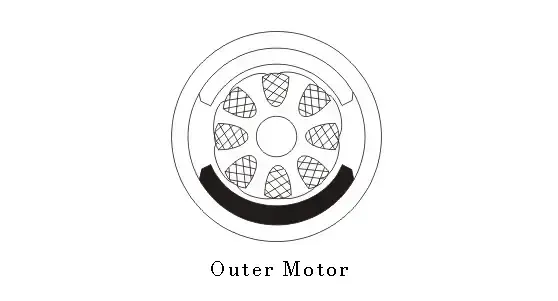
Outer Rotor Design: In outer rotor design, the rotor surrounds the winding which is loacted in the core of the motor. The magnets in the rotor trap the heat of the motor inside and do not allow to dissipate from the motor. Such type of designed motor operates at lowerrated current and has low cogging torque.
Working Principle and Operation of BLDC Motor: BLDC motor works on the principle similar to that of a conentional DC motor, i.e., the Lorentz force law which states that whenever a current carrying conductor placed in a magnetic field it experiences a force. As a consequence of reaction force, the magnet will experience an equal and opposite force. IN case of BLDC motor, the current carryinng conductor is stationary while the permanent magnet moves.
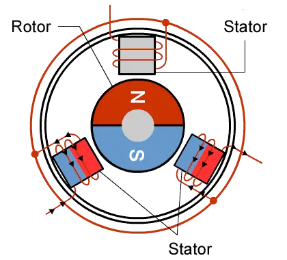
When the stator coils are electrically switched by a supply source, it becomes electromagnet and starts producing the uniform field in the air gap. Though the source of supply is DC, switching makes to generate an AC voltage waveform with trapezodial shape. Due to the force of interaction between electromagnet stator and permanent magnet rotor, the rotor continues to rotate. Consider the figure below in which motor stator is excited based on different switching states. With the switching of windings as High and Low signals, corresponding winding energised as North and South poles. The permanent magnet rotor with North and South poles align with stator poles causing motor to rotate. Observe that motor producces torque because of the development of attraction force(When North-South or South-North alignment) and repulsion forces(when North-North or South-South alignment). By this way motor moves in a clockwise direction.
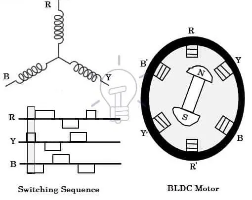
The motor continuous rotation depends on the switching sequence around the coils. Hall sensors give shaft position feedback to the electronic controller unit. Based on this signal from sensor, the controller decides particular coils to energize. Hall effect sensors generate Low and High level signals whenever rotor poles pass near to it. These signals determine the position of the shaft.
Brushless DC Motor Drive: As explained above that the electronic controller circuit energises appropriate motor winding by turning transistor or other solid state switches to rotate the motor continuously. The below figure shows the simple BLDC motor drive circuit which coonsists of MOSFET bride and also called as inverter bridge, electronic controller, hall elements and BLDC motor.
Here, Hall effect sensors are used for position and speed feedback. The electronic controller can be a microcontroller unit or microprocessor or DSP processor or FPGA unit or any other controller. This recieves signals, processes and sends the control signals to the MOSFET driver circuit. In addition to the switching for a rated speed of the motor, additional electronic circuitry changes the motor speed based on required application. These speed control units are generally implemented with PID controllers to have precise control.
Advantages: The advantages of a BLDC motor are,
- Brushless motors are more efficient as its velocity is determined by the frequency at which current is supplies, not the voltage.
- BLDC motor can operate at high speed under any condition.
- There is no sparking and much less noise during operation.
- As brushes are absent, the mechanical energy loss due to friction is less which enhanced efficiency.
- BLDC motorsaccelerate and decelerate easily as they are having low rotor inertia.
- More electromagnets could be used on the stator for more precise control.
- Due to absent of brushes BLDC motors are reliable, high life expectancies and maintenance free operation.
- There is no ionizing sparks from the commutator, and electromagnetic interference is also get reduced.
Disadvantages: The disadvantages of a BLDC motor are,
- BLDC motor cost more than a brushed DC motor.
- The limited high power could be supplied to BLDC motor, otherwise too much heat weakens the magnets and the insulation of winding may get damaged.
- Electronic controller required to control this motor which is expensive.
- Not much availability of many integrated electronic control solutions, especially for tiny BLDC motors.
- Need of additional sensors.
Applications: BLDC motors are used for a wide variety of application requirements such as varying loads, constant loads and positioning applications in the fields of industrial control, automotive, aviation, automation systems, health care equipments, etc. Some specific applications of BLDC motors are,
- Computer hard drives and DVD/CD players.
- Electric vehicles, hybrid vehicles and electric bicycles.
- Industrial robots, CNC machine tools and simple belt driven systems.
- Washing machines, compressors and dryers.
- Fans, pumps and blowers.
Future of BLDC motors: We can expect to see BLDC used in a wider range of applications in the future. For example, they will probably be widely used to drive service robots, small robots that deliver services in fields other than manufacturing, as BLDC motors are better suited to controlling the force. With BLDC motor all that would be required is a current proportionate to the external force allowing for more power efficient control. BLDC motors may also be replacing simple brushed dc motors in golf carts and mobility carts. In addition to their better effieciency, BLDC motors can also deliver more precise control. Which in turn extend the battery life. BLDC motors are also ideal for drones. Their ability to deliver precise control makes especially suited for multirotor drones, where the drones attitude is controlled by precisely controlling the rotational speed of each rotor.