Week-7 Challenge: DC Motor Control
Aim: To learn more about power electronics applications in electric vehicles, especially the DC motor operation using power electronics via comparison of two configurations namely the H-bridge and the four quadrant chopper model.
Question 1
The model "Speed control of a DC motor using BJT H-bridge" is opened in the MATLAB examples.
This example shows the simulation of an H-bridge used to generate a chopped voltage and to control the speed of a DC motor. The DC motor is of the rating 5 HP, 24V and 1750rpm. The armature mean voltage can be varied from 0 to 240 V when the duty cycle (specified in the Pulse Generator block) is varied from 0 to 100%.
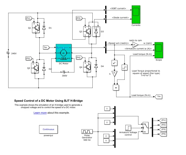
The BJTs here are modelled with IGBTs which consist of the switch and an anti-parallel diode.
The PWM signals to the switches Q1,Q2,Q3 and Q4 are given through the pulse generator and armature voltage control block.
Working of a typical H-bridge
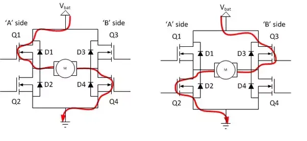
-When switch Q1 and Q4 are closed, this will cause the current to flow from the source through switch 1 and then through the load M and through switch Q4 and then down to the ground. This leads to the forward motion of the motor.
-When switch Q2 and Q3 are closed, this will cause the current to flow from the source through switch S3 and then through the load and then further through Q2 to the ground. This leads to a reverse motion of the motor.
- When the switches Q1,Q3 oe Q2,Q4 are closed, then both sides of the motor have the same voltage and this is the brake mode and the motor is coasting.
-Similarly if Q1,Q2 or Q3, Q4 are closed then it will cause a short and burn out the H-bridge.
Working of the Simulink model "Speed control of a DC motor using BJT H-bridge"
The motor starts in the positive( forward) direction with a duty cycle of 75% (mean DC voltage of 180V). At t= 0.5 sec., the armature voltage is suddenly reversed and the motor runs in the negative (reverse) direction.
The output from the speed is multiplied with a constant (k) to give the load torque and it is also connected with the 'Scope'. The 'Scope' shows the motor speed, the armature current and the load torque.
When the simulation is run, the following is obtained.
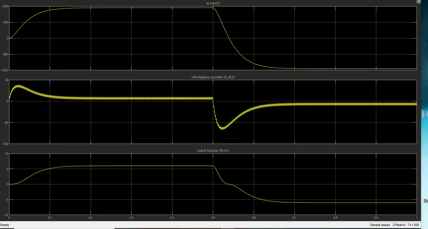
As can be seen, at the 0.5 second mark, the armature current changes from positive to negative which is indicative of the DC motor operating in a different mode from here on.
The armature current overshoots because of the sudden change in load however, it settles down when constant speed is reached.
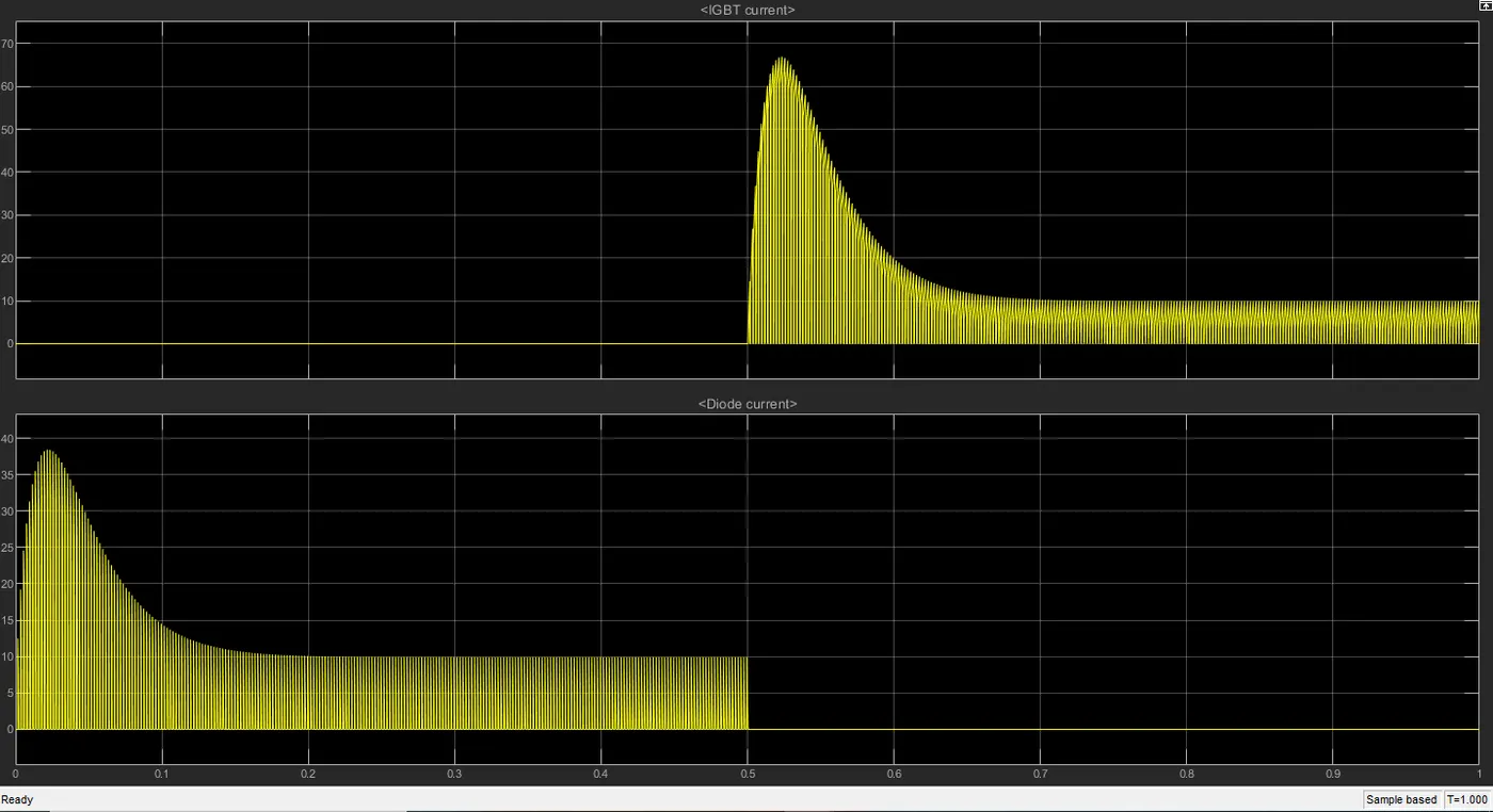
'Scope' block shows motor speed, armature current and load torque and 'Currents' block shows currents flowing in BJT Q3 and diode D3.
When the current is passing through D3, the switches Q1 and Q4 are on meaning the motor is running in the forward direction. The freewheeling diode D3 gives a path to the current while the motor operation goes from one state to the other. Without diodes the steep voltage rise across the switches could damage them.
Then when the current is passing through the switch Q3 from0.5 s to 1s, we can see that the motor is running in the reverse direction.
Duty cycle concept
A duty cycle is the fraction of one period in which a signal or system is active,here it defines the on-time of the input square wave. Duty cycle is commonly expressed as a percentage or a ratio. The duty cycle of the pulse geneerator and the control logic are combined to give the switching pulses to the switches. This can be used to reduce the overshoot in the armature current. The initial value of duty cycle for the square wave provided is 75%.
To reduce the initial overshoot in the armature current, one can try to reduce the duty cycle, maybe to 50%.
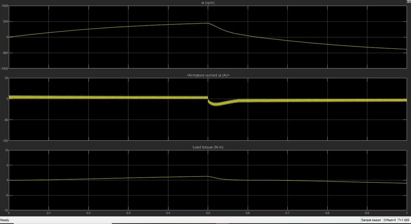
Hence we see that reducing the duty cycle leads to a decrease in overshoot for the armature current when the direction of operation changes. Also, the load torque and the speed does not have a sharp increase or decrease.
Question 2
The following is an image of the "The Four-Quadrant Chopper DC Drive (DC7) block" model.
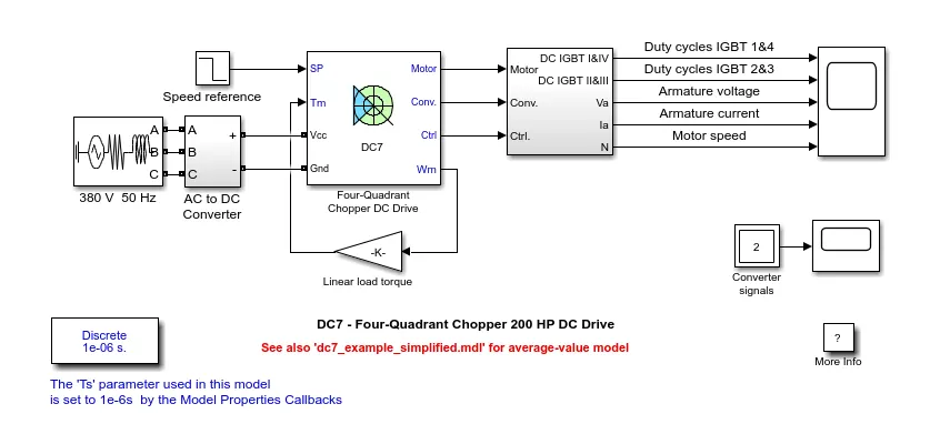
In the above model, 3 phase voltage source and a recitifier are connected to te Four Quadrant DC drive DC7 block. The armature voltage is provided by the IGBT converter controlled by two PI controllers namely a current controller and a speed controller.
Working of the Four quadrant Chopper DC-drive block
This type of converter can be operated in all four quadrants. The power can either flow from source to load or load to source in this chopper. It can convert a fixed DC to a variable DC output.
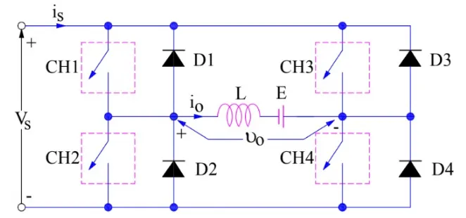
The circuit consists of four switches T1 to T4 and four diodes D1 to D4 connected anti-parallel to each of the switches respectively.
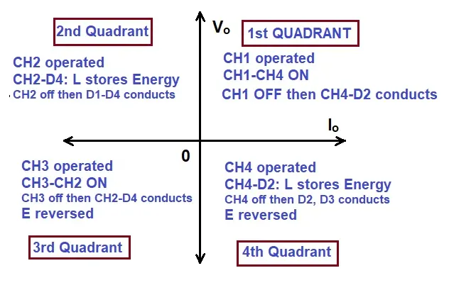
The operation of a four quadrant chopper or Class-E chopper is summarized in the figure above. The chopper operates in the four quadrants of the vo-io plane as shown in the following figure. Here vo Vo is the average output voltage, io is the output current and Io is the average output current of te Type E chopper circuit.
First Quadrant Operation:
For first quadrant operation, CH4 is kept ON, CH3 is kept OFF and CH1 is operated. When both CH1 & CH4 are ON simultaneously, the load gets directly connected to the source and hence the output voltage becomes equal to the source voltage. This essentially means that vo = vs. It may be noted that the load current flows from source to load as shown by the direction of io.
When CH1 is switched OFF, the load current free wheels through CH4 and D2. During this period, the load voltage and current remains positive. Thus, both the output voltage vs and load current io are positive and hence, the operation of chopper is in first quadrant. It may be noted that, Class-E chopper operates as a step-down chopper in this case.
Second Quadrant Operation:
To obtain second quadrant operation, CH2 is operated while keeping the CH1, CH3 & CH4 OFF. When CH2 is ON, the DC source in the load drives current through CH2, D4, E and L. Inductor L stores energy during the On period of CH2.
When CH2 is turned OFF, current is fed back to the source through D1, D4. It should be noted at this point that (E+Ldi/dt) is more than the source voltage Vs. As load voltage Vo is positive and Io is negative, it is second quadrant operation of chopper. Since, the current is fed back to the source, this simply means that load is transferring power to the source. Kindly read Step-up chopper for detailed analysis and better understanding.
For second quadrant operation, load must contain emf E as shown in the circuit diagram. In second quadrant, configuration operates as a step-up chopper.
Third Quadrant Operation:
To obtain third quadrant operation, both the load voltage and load current should be negative. The current and voltage are assumed positive if their direction matches with what shown in the circuit diagram. If the direction is opposite to what shown in the circuit diagram, it is considered negative. One important thing to notice is that the polarity of emf E in load must be reversed to have third quadrant operation. Circuit diagram of Class-E chopper for third quadrant operation is shown below.
For third quadrant operation, CH1 is kept off, CH2 is kept ON and CH3 is operated. When CH3 is ON, load gets connected to source and hence load voltage is equal to source voltage. But carefully observe that the polarity of load voltage vo is opposite to what shown in the circuit diagram. Hence, vo is assumed negative. Let us now see what is the status of load current io. It may be seen that io is flowing in the direction opposite to shown in the circuit diagram and hence negative.
Now, when CH3 is turned OFF, the negative load current free wheels through the CH2 and D4. In this manner, vo and io both are negative. Hence, the chopper operates in third quadrant.
Fourth Quadrant Operation:
To obtain fourth quadrant operation, CH4 is operated while keeping CH1, CH2 and CH3 OFF. The polarity of load emf E needs to be reversed in this case too like third quadrant operation.
When CH4 is turned ON, positive current flows through CH4, D2, L and E. Inductance L stores energy during the time CH4 is ON. When CH4 is made OFF, current is fed back to the source through diodes D2, D3. Here load voltage is negative but the load current is always positive. This leads to chopper operation in fourth quadrant. Here, power is fed back to the source from load and chopper acts as a step-up chopper.he operation of a four quadrant chopper or Class-E chopper is summarized in the figure below.
The speed reference is set at 500rpm at t=0s. Observe that the monitor speed follows the reference ramp accurately (400 rpm/s) and reaches steady state around t=1.3s.
The armature current follows the current reference very well, with fast response time and small ripples. The current ripple frequency is 5kHz.
Why the four-quadrant chopper is better than the H-bridge model?
-The four quadrant chopper has more operating modes (forward motoring, forward braking, reverse motoring, reverse braking) but H-bridge can operate only in two modes (forward and reverse).
- Pi controllers are implemented to obtain the electromagnetic torque needed to reach the desired speed and control the armature curent and stabilize the system but in H-bridge no PI controller is used.
- Regenerative braking is possible with the four quadrant chopper but not with the H-bridge model.
- The four quadrant chopper has a higher efficiency as compared to the H-bridge.
Question 3
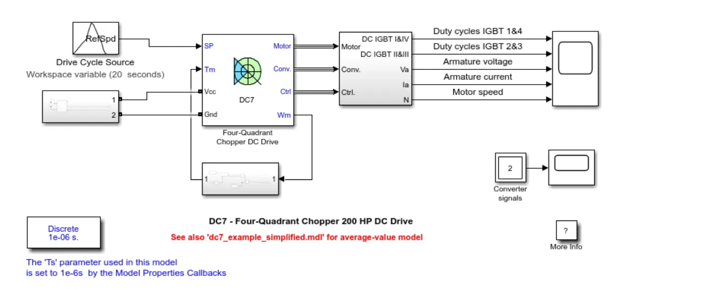
As seen above, the four quadrant chopper model is modified.
The drive cycle data is taken from an excel file that is created seprarately. This data is imported into the simulink file. The data consists of time and speed data and is given to the drive cycle source. It is given in rpm vs seconds.
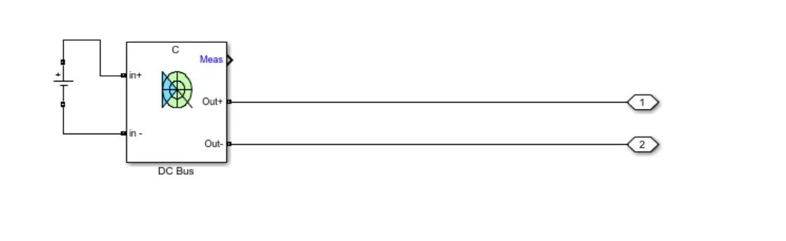
The three phase AC voltage source is replaced with a battery since the energy source of an EV is a battery,a resistance is added in series with the DC voltage source and this is connected to a braking chopper. The following configuration is created.
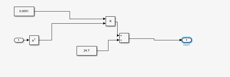
The linear load torque is replaced with vehicle load characteristics for the torque and speed of the vehicle. The simulink blocks are connected according to the following equation.
T=24.7+0.0051w^2
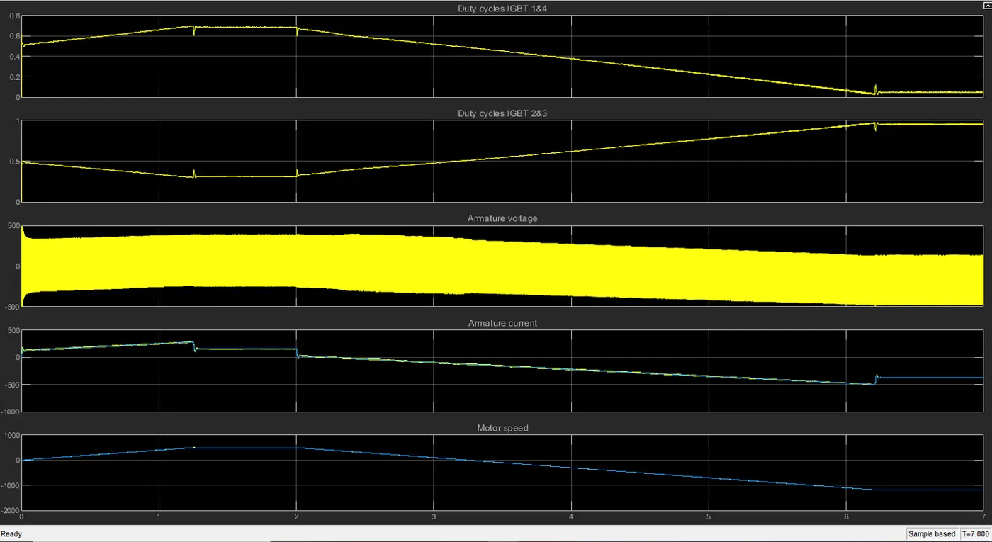
On running the simulation the following plot is obtained.
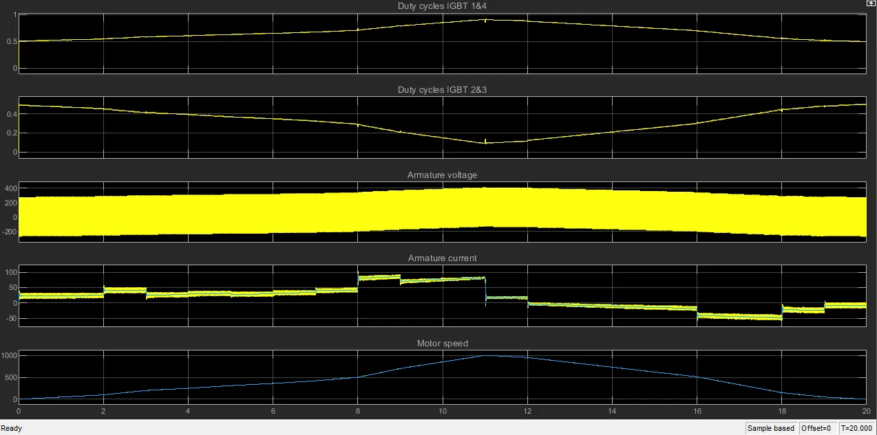
When the motor speed increases, the IGBT 1&4 duty cycle also increases. The switches 1&4 and 2&3 are complimentary so when the duty cycle of IGBT 1&4 increase that of 2&3 decreases.
When the motor speed increases the armature voltage also increases because the it takes more voltage from the DC voltage source. The motor speed follows the drive cycle reference given.
All the files can be accessed at the following link:https://drive.google.com/drive/folders/17Hfqf8rCWbatATKrDbu0YZtwg3taU2EM?usp=sharing