Week-7 Challenge: DC Motor Control
- Explain a MATLAB demo model named ‘Speed control of a DC motor using BJT H-bridge’.
Controlling and conversion of electrical power is an application of power electronic, and it is done by switching devices like IGBT, MOSFET
H-bridge
It is an electronic circuit that switches the polarity of a voltage applied to the load.
A bipolar stepper motor always driven by a motor controller containing two h-bridge.
Duty Ratio (d) = (ON) time/(ON+OFF) time
By changing the Duty Ratio of the Power Modules, we can vary the Voltage from one level to another level.
Vavg = Vbat * d
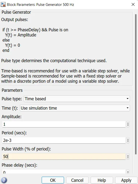
The Bipolar Junction Transistor (BJT) when used for power switching applications, operates as an IGBT. When it is conducting (BJT operating in the saturated region), a forward voltage Vf is developed between collector and emitter (in the range of 1 V). Therefore, the IGBT block can be used to model the BJT device. The IGBT block does not simulate the gate current controlling the BJT or IGBT. The switch is controlled by a Simulink® signal (1/0). The DC motor uses the pre-set model (5 HP 24V 1750 rpm). It simulates a fan type load (where Load torque is proportional to square of speed). The armature mean voltage can be varied from 0 to 240 V when the duty cycle (specified in the Pulse Generator block) is varied from 0 to 100%
The H-bridge consists of four BJT/Diode pairs (BJT simulated by IGBT models). Two transistors are switched simultaneously: Q1 and Q4 or Q2 and Q3. When Q1 and Q4 are fired, a positive voltage is applied to the motor and diodes D2-D3 operate as free-wheeling diodes when Q1 and Q4 are switched off. When Q2 and Q3 are fired, a negative voltage is applied to the motor and diodes D1-D4 operate as freewheeling diodes when Q2 and Q3 are switched off
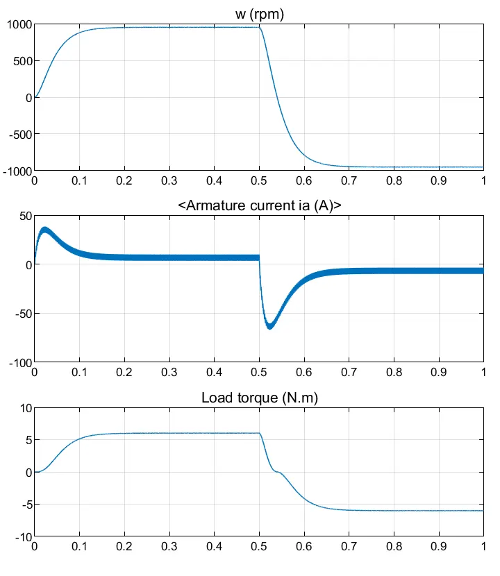
Comment on the armature current shoot-up from the scope results.
Motor & Simulation Specs:
Power = 5 HP Rated Voltage = 240 V
Rated Speed = 1750 RPM
The motor starts in the positive direction with a duty cycle of 75%
DC voltage of 180V At t= 0.5 sec., the armature voltage is suddenly reversed and the motor runs in the negative direction
In motor, armature current (I) is given by: -
I=(V-E)/R.
Where, V is the voltage supplied, E is the back emf and R is the armature resistance.
Thus, I depends upon E and R when V is kept constant. When the motor starts its speed remains zero i.e., E also remains zero (since, back emf is ∝ speed of the armature).
Thus, initial starting armature current: -
I=(V-0)/R= V/R. (as, E =0)
Since, the armature resistance of a motor is very small, generally less than one ohm, therefore the starting current would be very large. As the motor speed increases, the back emf increases and the difference (V-E) goes on decreasing. This results in the gradual decrease of armature current until the motor attains its stable rated speed. Under this condition the armature current reaches its desired rated value.
Another Shoot up can be observed in the Armature Current when motor changes direction from forward to reverse. In order to avoid this,
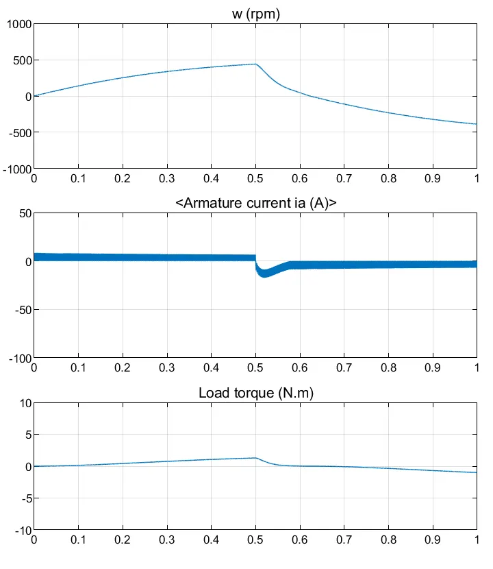
Duty ratio can be optimized Duty Ratio changed from 75% to 45 %
By reducing the Duty Ratio, Armature Current Shoot-Up can be completely optimized.
But there will be considerable fall in the Load Torque and hence the Speed.
No load Torque of the Motor has been reduced from 6 Nm to 2 Nm.
No load Speed is reduced from 900 RPM to 400 RPM
Reducing the Duty Ratio of the Power Modules, ultimately reduces the effect of shooting Armature current but reduces the Supply Voltage in to the Motors and results in the reduction of the Rated Speed and Torque of the Motor
A brushless DC electric motor (BLDC motor or BL motor), also known as an electronically commutated motor (ECM or EC motor) or synchronous DC motor, is a synchronous motor using a direct current (DC) electric power supply. It uses an electronic closed loop controller to switch DC currents to the motor windings producing magnetic fields which effectively rotate in space and which the permanent magnet rotor follows. The controller adjusts the phase and amplitude of the DC current pulses to control the speed and torque of the motor. This control system is an alternative to the mechanical commutator (brushes) used in many conventional electric motors.
The construction of a brushless motor system is typically similar to a permanent magnet synchronous motor (PMSM), but can also be a switched reluctance motor, or an induction (asynchronous) motor. They may also use neodymium magnets and be outrunners (the stator is surrounded by the rotor), inrunners (the rotor is surrounded by the stator), or axial (the rotor and stator are flat and parallel).[1]
The advantages of a brushless motor over brushed motors are high power-to-weight ratio, high speed, nearly instantaneous control of speed (rpm) and torque, high efficiency, and low maintenance. Brushless motors find applications in such places as computer peripherals (disk drives, printers), hand-held power tools, and vehicles ranging from model aircraft to automobiles. In modern washing machines, brushless DC motors have allowed replacement of rubber belts and gearboxes by a direct-drive design.