Project
SYSTEM-LEVEL SIMULATION OF AN ALL-TERRAIN VEHICAL
AIM:
To study and prepare a technical report explaining the model properties of an ATV (all-terrain vehicle).
OBJECTIVE:
Here we carry out a system level simulation of an ATV using a Simulink model and preparing a result of the model. In this model we learn more on CVT and its properties.
AN ALL-TERRAIN VEHICAL:
An ATV is a light utility vehicle used for off roading with low pressure tires and straddled seat position and uses handlebars for steering control.
ATV uses one cylinder 4-stroke engine with CVT gear box. Most of the ATV produces around 100Nm of torque.
CONTINUOUSLY VARIABLE TRANSMISSION(CVT):
A CVT transmission, or continuously variable transmission, seamlessly changes through an unending range of effective gear ratios while you drive, whereas other kinds of mechanical transmissions offer a fixed number of gear ratios and have hard shifts between each.
CVT has infinite no of gears ratio, therefore it can produce better acceleration and torque in lower gears and good fuel economy in higher speed.
In a CVT the energy is transmitted through a pully and connected by v-belt.
The pulleys consist of two cone-shaped halves that move together and apart. The V-belt runs between these two halves, so the effective diameter of the pulley is dependent on the distance between the two halves of the pulley.
The pulleys are adjusted by reducing and increasing the diameter in order to maintain proper tension of the belt and gear ratio.
CASE 1:
BAJA ATV MODEL – SIMULINK MODEL
The model is build using basic blocks of Simulink it also uses some mechanical blocks
COMPONENTS USED:
GENERIC ENGINE: An engine is a basic component used in a vehicle. This block is a system level representation of SI or diesel engines. It is used with basic parameters.
In this model engine is the input for the CVT block
Point B is the input and F is the output from, the engine point F has a rotational force this is then connected to the CVT gearbox.
CVT BLOCK:
CVT block contains
- Variable ratio gear
- Ideal rotational motion sensor
Variable ratio gear: This block represents a variable gear box.
Ideal rotational motion sensor: it measures the angular velocity of the primary and secondary shaft.
The gear ratio for the gearbox is taken as 10 in this model, the output rotational force is transmitted to the vehicles body through a simple gear
VEHICLE BODY:
In this block the force created by the engine with respect to the amount of throttle given and brake applied is transmitted to the wheels
We can observe the velocity that can be produced by the CVT gearbox with respect to all the given parameters like drag, road incline etc.
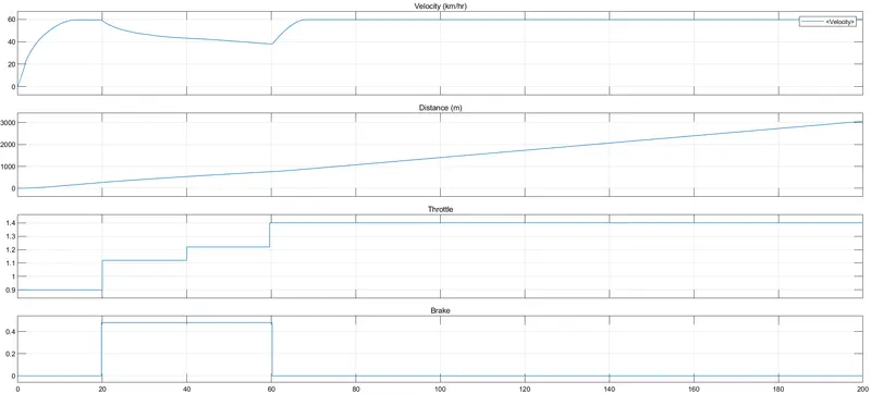
In this case the input signal are given through signal builder block by adjusting the throttle value and brake values
As we see in the image the throttle is increased with time hence the velocity is also increased with respect to the applied throttle, for the time period of 20s to 60s an amount of brake is applied which reduces the velocity.
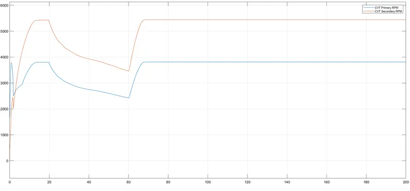
Graph 2 shows the RPM of the engine along with RPM of wheel.
When the engine RPM hit’s max value the wheel requires less speed from the input to maintain constant output speed hence the primary RPM is greater in the beginning of the movement and reduces after engine becomes stable
Case 2:
DASHBOARD INPUT
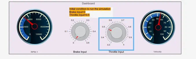
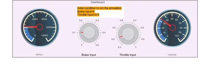
All the inputs can be changed while the simulation is running using the dashboard controls, and we can also see the change in the RPM and velocity of vehicle as the input throttle and brake values are changed.
At initial condition the throttle input is 0.5 and brake input is 0 there is and RPM gets to 3000 and velocity increases to 50
When a particular value is given to brake the velocity decreses