Week - 4
Implement control logic of a “washing machine” using Stateflow as per given sequence:
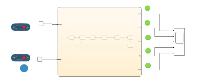
In this challenge we created a control logic for a washing machine using state flow. For this we used a state flow chart from the Simulink library
When the value for the input power and input water is 1 the state flow moves to the next step if not
If the water is not available the process is stopped and indicated through LED.
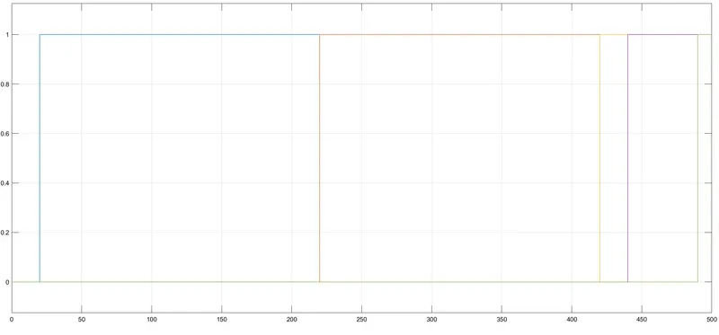
The first 200 sec soaking process takes place for the next 100 sec is washing process
Rinsing and drying takes placed for the last 20sec and 50 sec respectively.
For the completion of each process they are indicated by LED, therefore when all the process are completed all the given LED will be turned ON
Make a Simulink chart for the “Gear shift” logic as per below conditions
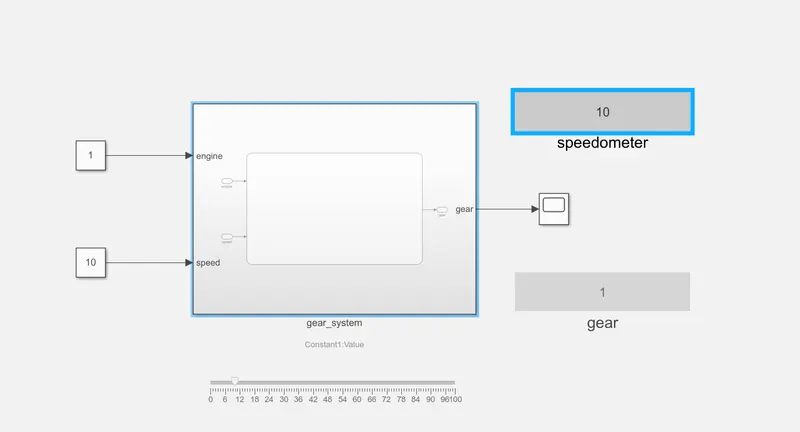
To produce a state flow for gear we need to understand the working of a gear system.
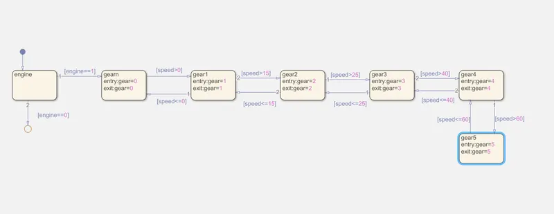
Every gear has a max and min speed value, this speed value will be used as the condition statement for the state flow.
The first condition will be engines ON or OFF condition
If the engine is ON the state flow moves to the neutral gear where the entry and exit speed is 0.
When the speed is greater than 0 and less than 15 the gear 1 will be used.
If the speed is greater than 15 and less than 25 the gear 2 will be used.
If the speed is greater than25 and less than 40 the gear 3 will be used.
If the speed is greater than 40 and less than 60 the gear 4 will be used.
If the speed is greater than 60, gear 5 will be used.
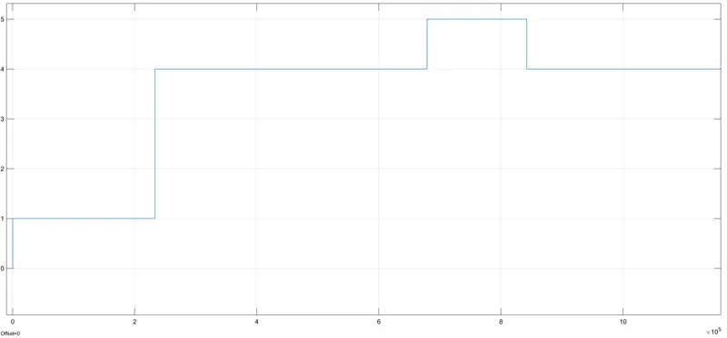
The flow is stopped at the 5th gear
The speed is varied as we run the process by using the slider from the slider block from the dash board panel and we can also use slider switch to switch ON the ignition.