Week-7 Challenge: DC Motor Control
1. The model shows the simulation of speed control of DC motor using H bridge converter. H bridge converter uses a IGBT switch as semiconductor device. The gate turn off for the IGBT is provided by simulink signal 1 or o. A preset model of (5 HP 24V 1750 rpm)is used for the motor model. It simulates a fan type load (where Load torque is proportional to square of speed). The armature mean voltage can be varied from 0 to 240 V when the duty cycle (specified in the Pulse Generator block) is varied from 0 to 100%.
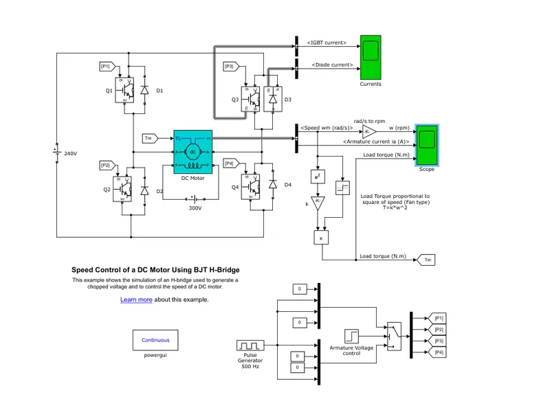
During the positive half cycle the switches Q1 and Q4 will be conducting and armature voltage can be varied by changing the duty cycle. D2 and D3 will be freewheeling when the switcheds Q1 and Q4 are off . During negative half cycle switches Q3 and Q2 will be conducting. when Q3 and Q2 are off, D1 and D2 will be free wheeling.
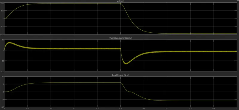
The result can be seen in scope.The motor starts in the positive direction with a duty cycle of 75% (mean DC voltage of 180V). At t= 0.5 sec., the armature voltage is suddenly reversed and the motor runs in the negative direction.
2. In four quadrant DC chopper drive, closed loop speed control with four quadrant operation ie forward motoring and regeneration, reverse motoring and regeneration is achieved.
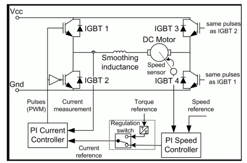
Closed loop speed control is implemented using PI Controller whoch generates reference armature current for PI current controller. PI current controller produces PWM signals for the IGBTs and there by control the voltage fed to IGBT.
3. Two quadrant chopper or therwise known as TYpe C chopper provides current in both motoring and braking mode where as the output voltage is always positive. Switch in the same leg cannot be turned on simultaneously. When the chopper is on the freewheeling diode starts conducting and the output voltage v0 will be equal to Vs . The direction of the load current i0 will be reversed. The current i0 will be flowing towards the source and it will be positive regardless the chopper is on or the FD conducts. The load current will be negative if the chopper is or the diode D2 conducts. We can say the chopper and FD operate together as type-A chopper in first quadrant. In the second quadrant, the chopper and D2 will operate together as type –B chopper.
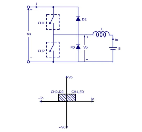
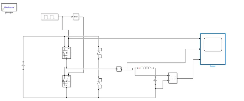
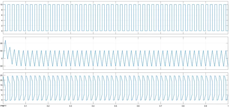
The simulink model for two quadrant chopper is shown in the figure.
Load Voltage source=12V
Input voltage=24V
Pulse generator amplitude= 10V
Pulse width =50%
3. DC brushless motor is electronically commutated motor where integrated inverter/switching circuit is used to achieve unidirectional torque. It achieves electronic commutation by sensing the rotor position and energizing the corresponding stator windings. A BLDC motor also consists of two main parts a stator and a rotor. Permanent magnets are mounted on the rotor of a BLDC motor, and the stator is wound for a specific number of poles. Also, a control circuit is connected to the stator winding.
There are several advantages of BLDC motor
- Higher efficiency and reliability
- Lower acoustic noise
- Smaller and lighter
- Greater dynamic response
- Better speed versus torque characteristics
- Higher speed range
- Longer life
BLDC motor works on the principle similar to that of a conventional DC motor, i.e., the Lorentz force law which states that whenever a current carrying conductor placed in a magnetic field it experiences a force. As a consequence of reaction force, the magnet will experience an equal and opposite force. In case BLDC motor, the current carrying conductor is stationary while the permanent magnet moves.
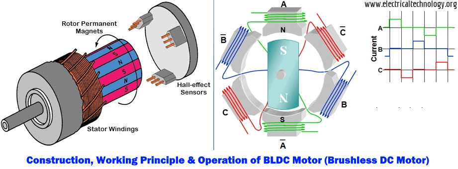
When the stator coils are electrically switched by a supply source, it becomes electromagnet and starts producing the uniform field in the air gap. Though the source of supply is DC, switching makes to generate an AC voltage waveform with trapezoidal shape. Due to the force of interaction between electromagnet stator and permanent magnet rotor, the rotor continues to rotate.
The stator is excited based on different switching states. With the switching of windings as High and Low signals, corresponding winding energized as North and South poles. The permanent magnet rotor with North and South poles align with stator poles causing motor to rotate.Based on this signal from sensor, the controller decides particular coils to energize. Hall-effect sensors generate Low and High level signals whenever rotor poles pass near to it. These signals determine the position of the shaft.