Project
Modeling of a Continuously Variable Transmission (CVT) BAJA All-Terrain Vehicle (ATV)
Modeling of a Continuously Variable Transmission (CVT) BAJA All-Terrain Vehicle (ATV)
Summary
This technical report details the modelling and simulation of a Continuously Variable Transmission (CVT) BAJA All-Terrain Vehicle (ATV) using Simscape and Simscape driveline. This models help to analyse the effect of various vehicle parameters such as weight, CVT ratio etc on the performance of the vehicle. There are two configurations considered in the study (i) Open loop configuration where the CVT ratio is varied randomly and effect of vehicle performance is analysed. (ii) Closed loop configuration where CVT ratio is selected based on look up table. This model helps to explore and analyse various designs and parameters. This simplified simulation model can be further extended to model real world conditions.
Objective
- To describe and model the components of BAJA ATV
- To study the effect of parameter variations on the performance of vehicle in open loop and closed loop configuration.
- To study the implementation of real time time data on simulation model.
Introduction
ATV means All-Terrain Vehicle specially designed for an off-road driving and is meant for very rough terrain. The vehicle modelling is carried out using Simscape and Simscape driveline and helps to analyse BAJA ATV powertrain system. CVT is an automatic, single speed, gearless transmission that can shift through an infinite number of gear ratios. It which an arrangement of pulleys and belts made it possible for a drive to achieve n-number of continuous gear ratios within a range[1].
Vehicle Specifications
The vehicle specifications are provided by the team Synergy,G L Bajaj Institute of Technology and Management. They are listed in the table below.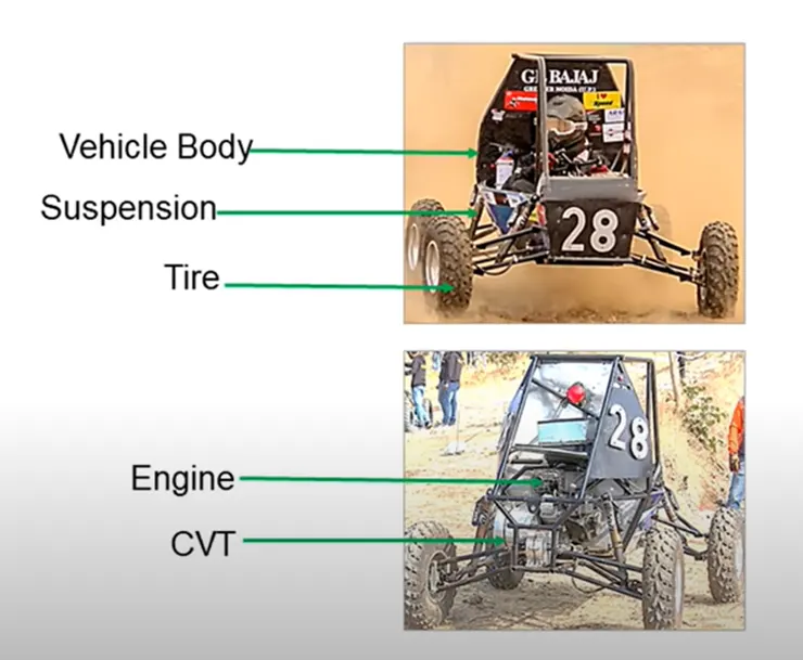
|
Vehicle Weight (kg) |
250 |
|
Frontal area (m2) |
0.735482 |
|
Tire radius (m) |
0.2921 |
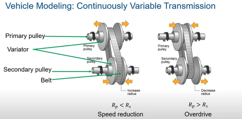
The major components of BAJA ATV consist of vehicle body, suspension, tire, engine and CVT. CVT consist of primary pulley, variator, secondary pulley and belt. When the variator of primary pulley goes outward, the variator of secondary pulley moves inwards and radius of secondary pulley increases and result in decrease of speed. When the variator of secondary pulley moves inwards, the variator of secondary pulley moves inwards the variator of secondary pulley moves outward and radius of secondary pulley reduces which results in overdrive condition.
Open Loop Configuration
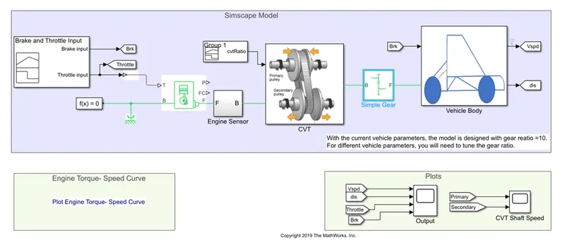
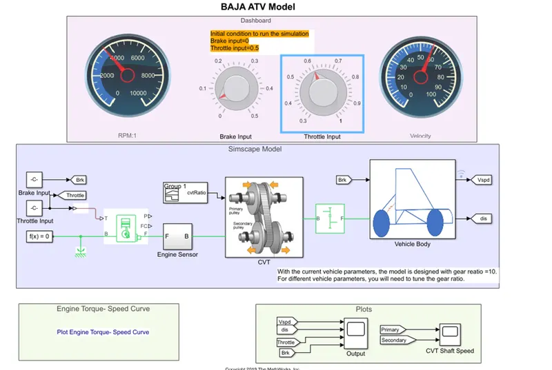
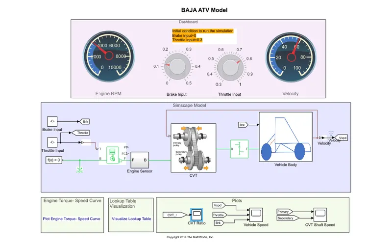
In open loop configuration CVT ratio is given randomly and not based on vehicle performance. The Simulink model of BAJA ATV operating in open loop mode is shown below. Here the brake input and throttle input is given in two modes. One model uses signal builder block ie without dashboard and whereas other model (i.e. model with dashboard) uses circular gauge to give constant value of throttle and break input.
Model 1
Model 2
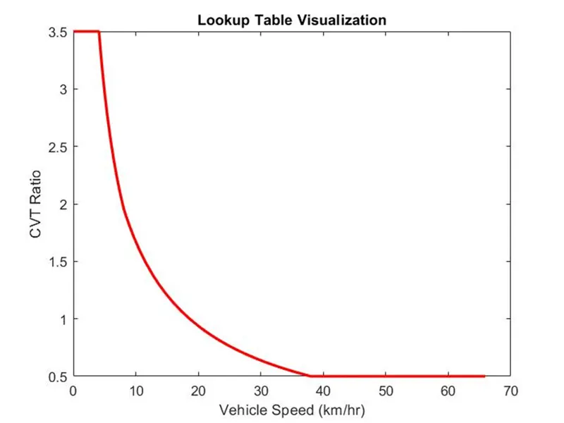
n the third model, a look up table is created based on the values of vehicle velocity(km/hr) and CVT ratio. Signal builder block used in the previous configuration is replaced by CVT look up table.
The look up table is created using the values of vehicle speed in kmph and CVT ratio from previous open loop model.
The major components of the system include
- Engine Model
- CVT
- Simple Gear
- Vehicle Body
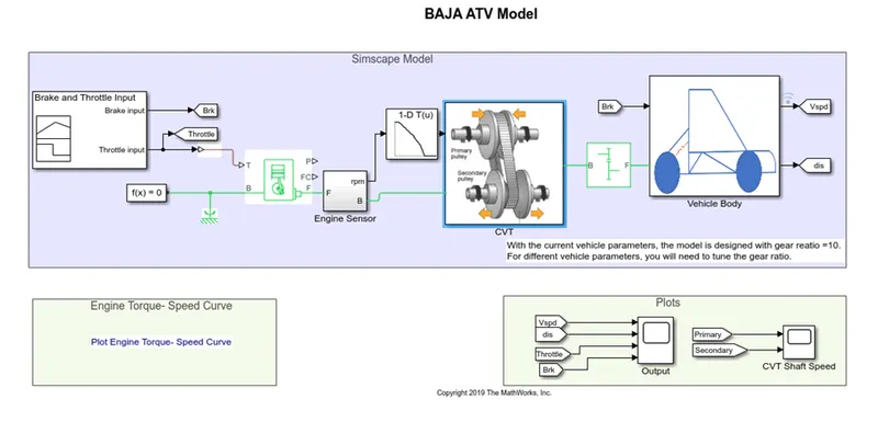
Input is given as brake and throttle input. Brake input is given in this case as 0 and throttle input is given as 1. Brake and throttle input is built using signal builder block. The speed and throttle input is then given to generic engine block. The speed vector and torque vector is inputted from vehicle data.If the vehicle data is presented in the form of image, file extension GRABIT , can be used to extract data points and the data points can be given as input parameter for engine block.CVT model is built by Variable ratio gear with primary and secondary pulley modelled by input and output shaft inertia. A simple gear is used as mechanical connection between engine and CVT. Gear ratio is selected after analysis of vehicle velocity, engine rpm and torque output. The maximum velocity of BAJA vehicle is approximately in the range of 3840 rpm. Gear ratio is selected in such a way that vehicle doesn’t overdrive or underdrive . In this case, gear ratio is considered to be 12.
Vehicle Modelling
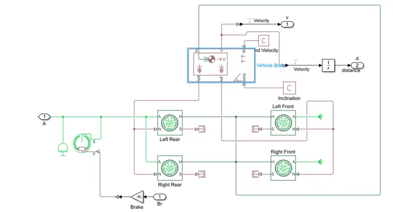
In vehicle model block parameters such as car mass, frontal area, number of wheels per axle, drag etc can be specified. Tyre modelling is done with default values. However it can be defined for user defined values.
Result and Analysis
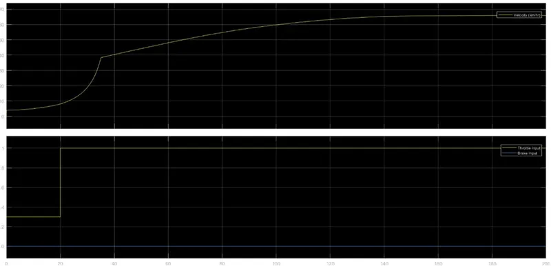
Output curves shows the increase in output velocity with increase in throttle input. Below is the output for CVT model without dashboard. Brake input is given 0 and throttle is constant 0.3 till 20 sec and being increased to 1 through out the simulation. Vehicle speed increases to 65kmph.
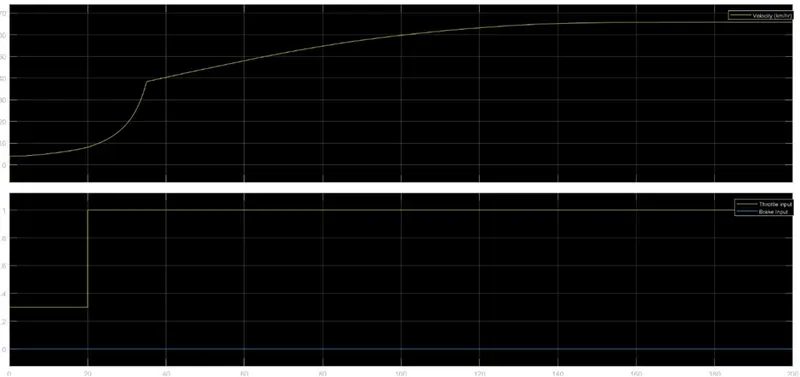
In case of Simulink model with dashboard throttle and brake inputs are user controlled. Whenever brake input is applied vehicle slows down and based on throttle input given through knob, velocity of vehicle increases.
Closed Loop Configuration
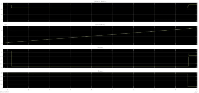
In closed loop configuration CVT ratio is decided by vehicle velocity. This is represented by two ways- without dashboard and with dashboard. A feed back is provided from the vehicle input and based on this input CVR ratio are selected.
The Simulink model of BAJA ATV operating in closed loop mode(without dashboard) is shown below.
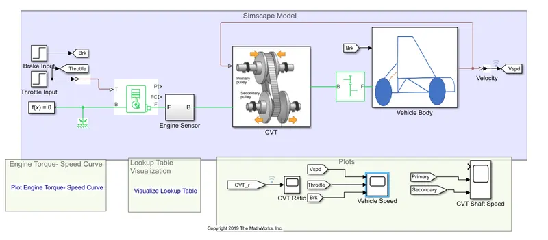
The Simulink model of BAJA ATV operating in closed loop mode (without dashboard) is shown below. Here also throttle and brake inputs are governed by the user
The variation of vehicle speed with respect to throttle and break input is shown in the figure.
Conclusion
Modeling of BAJA ATV model helps the designers to get overall performance of the vehicle. Parametric studies can be carried out easily. Moreover, the model can be defined for user inputs.