Week -2
1. Doorbell using solenoid block
Aim:
- To make a simulink model of door bell actuated by solenoid block
- To simulate a situation where the switch is closed for 2 seconds, and to observe the movement of metal arm hitting the bell.
Explanation
A battery is connected to solenoid through a switch. A solenoid is an electromagnetic device comprising of coil of wire, housing and moveable plunger. When an electric current flows, an electromagnetic field is produced moving the plunger, hitting the ball. Here additional condition is that the switch must be closed for 2 seconds and then released.
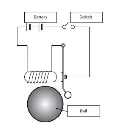
For simulating this, following blocks are used.
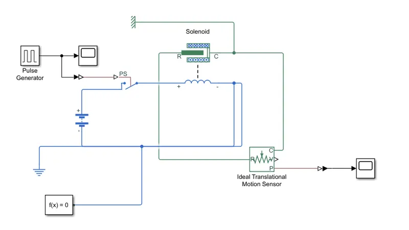
- Battery
- Solenoid
- Switch controlled by physical signal
- Pulse generator which gives control signals to switch. The time duration of pulse is characterised by 4sec and pulse width is 50%
- Ideal translational motion sensor to visualise the movement of plunger system
- Electrical and mechanical translational reference
- Solver configuration
The simulink model for the system is shown below.
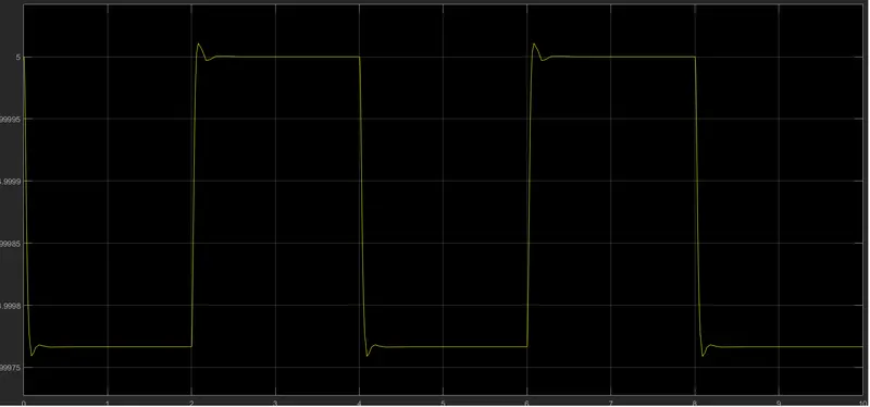
The output graph for the model is shown below which shows that for a time duration of 2 sec, the switch is closed, the electromagnet receives electrical power from the battery and pulls the metal arm to hit the bell producing sound. After 2 second the plunger is released. The released movement of plunger is shown in the figure below from 2 to 4seconds.
2. Thermistor controlled fan
Aim
- To use a thermistor to sense the temperature of a heater and turn on the fan as per the specified conditions
-
Time(s) Temperature(degC) 0-10 20 10-30 27 30-50 23
Explanation
Thermistor is a temperature sensitive resistor whose resistance varies with variation in the temperature. Whenever there is a change in temperature , thermistor heats up and there is an increasing the voltage across the resistor terminals. This voltage signal acts as control signal for switch which controls the circuit for dc motor which drives the fan.
For simulation, following blocks are used
- Thermistor
- Controlled temperature source
- Voltage Sensor
- DC Motor
- Ideal rotational motion sensor
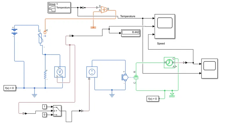
Now in the question, there are some specified conditions for temperature for various time instants. This condition is modelled in signal builder block by appropriately choosing the temperature value corresponding to the time duration. This temperature input causes change in voltage across resistance. The fan must be turned ON if temperature exceeds 25 degc. The corresponding change in voltage across R is found out and same voltage is applied as threshold for switch. If the voltage exceeds threshold, switch is closed, DC motor circuit is actuated which drives the fan. If the applied voltage is less than 25degC,switch is left open, and DC motor is turned off.
Result
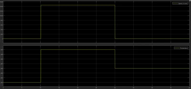
The waveforms for speed of motor and temperature profile is shown below. It can be seen that when temperature exceeds 25degC, switch is closed, Motor is connected to DC supply.when temperature lowers than 25 deg C, switch and controlled voltage source is turned OFF , Motor is connected to supply and fan is turned OFF.