Week - 4
1.
Aim:
To implement the control logic of washing machine using stateflow.
Logic:
Logic explained in the question is explained below
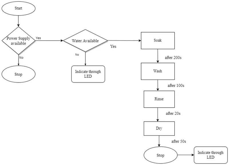
Implementation
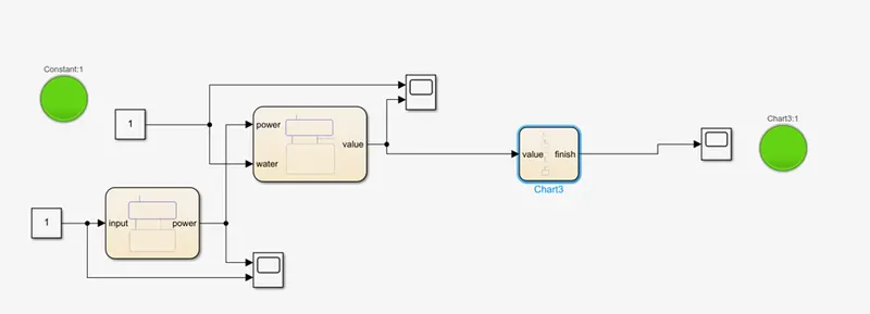
In order to implement the above logic, 3 charts have been used. In first one condition is made to check whether power supply is available, if it is available the output is turned
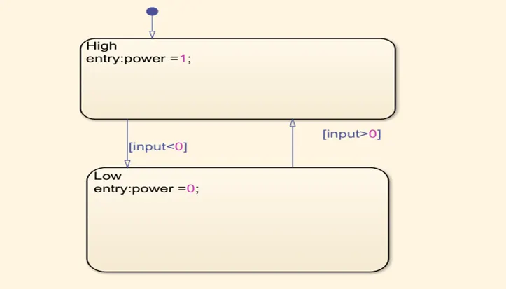
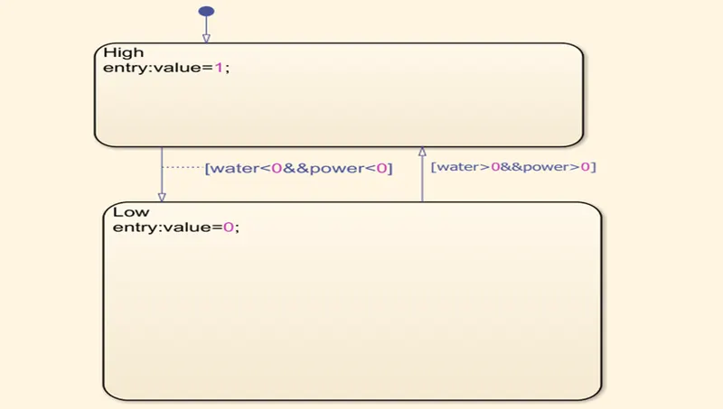
one and availability of water is checked next. If it is satisfied, another chart to check the availability of water is checked, if water is available i.e. output of chart 2 is 1,
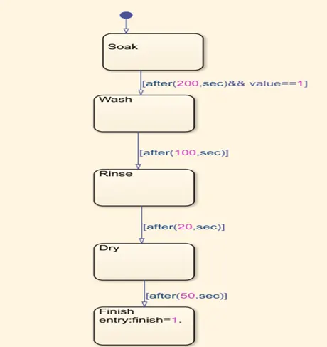
LED is connected at the water input state and output state to indicate the availability of water and end of process respectively.
2. Aim: To implement gear shift logic as per the input data.
|
Speed(Kmph) |
Gear |
|
0-15 |
1 |
|
16-25 |
2 |
|
26-40 |
3 |
|
41-60 |
4 |
|
Above 60 |
5 |
Implementation
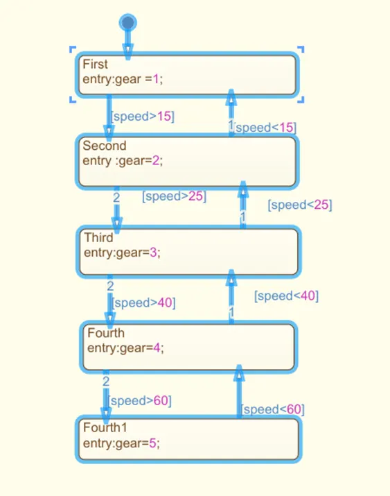
Based on the speed conditions gear is changed from one to other. This is implemented in the Simulink chart.
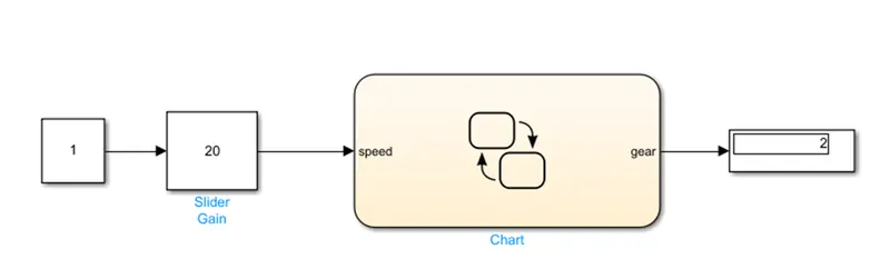
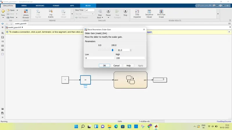
Input of the gear is given through slider gain where the gain can be adjusted manually. The logic of gear shift is implemented as shown below. The gear selected based on the input speed is displayed through display.
The simulation time is made infinity and different operating modes is captured. Attached are the images for two test cases
Case 1: when the speed is 20kmph and gear selected is 2
Case 2: when the speed is 81kmph and gear selected is 5
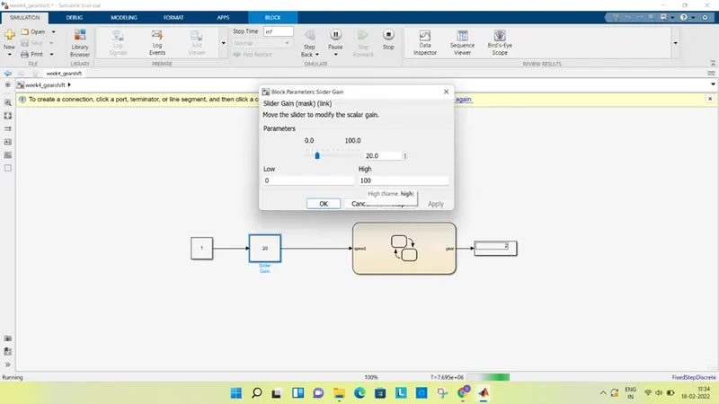
Case 1
Case2