Week-7 Challenge: DC Motor Control
1A). Explain a MATLAB demo model named ‘Speed control of a DC motor using BJT H-bridge’
H-BRIDGE
-
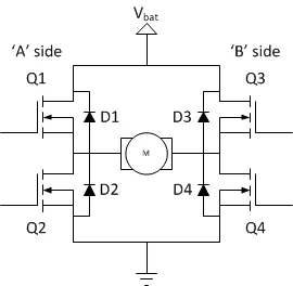
- It consists of 4 transitsors (Q1,Q2,Q3,Q4) and diodes (D1,D2,D3,D4) those transistors are driven by a gate controlled circuit like shown in above fig.
-
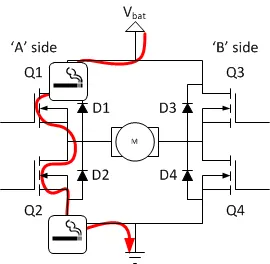
- When the transistor in the same leg are operated in the same time,It becomes the low resistance path and it gets short circuit .
- If the load acts as an source the current flows in reverse direction .
-
- These results in damaging the switches (transistor).
- To avoid this situation the diodes are used.
- The diode will conduct only in forward direction it doesnot allow if the current is in reverse direction.
- We can also avoid the higher voltage which can be applied across the switch.
- The Load is connected in parallel to the transistors.
- The DC machine (Load) can be operated in two modes
- Forward Direrction
- Reverse Direction
- FORWARD DIRCETION
-
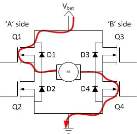
- If Q1 and Q4 are turned on, the left lead of the motor will be connected to the power supply, while the right lead is connected to ground. Current starts flowing through the motor which energizes the motor in (let’s say) the forward direction and the motor shaft starts spinning.
- In this state both Q2 and Q3 are turned Off.
- The power flow will be like Vbat - Q1 - Load - Q4 - Gnd.
-
- REVERSE DIRECTION
-
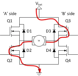
- If Q2 and Q3 are turned on, the reverse will happen, the motor gets energized in the reverse direction, and the shaft will start spinning backwards.
- In this state both Q1 and Q4 are turned Off.
- The power flow will be like Vbat - Q3 - Load - Q2 - Gnd.
-
AIM
To expalin the MATLAB demo model named ‘Speed control of a DC motor using BJT H-bridge’.
MODEL
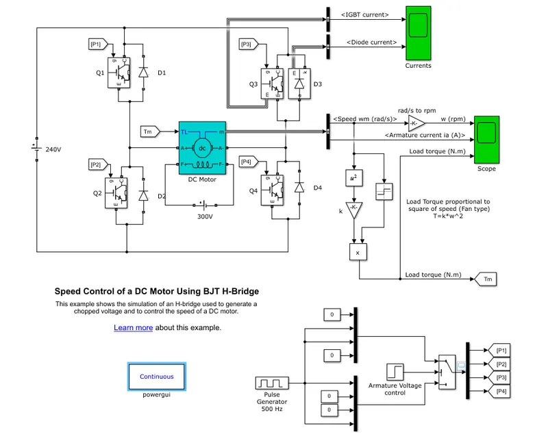
BLOCKS USED
- IGBT
- This model consists of 4 IGBT , which is represented as Q1,Q2,Q3,Q4.
- The forward voltage Vf is developed between collector and emitter (in the range of 1 V). Therefore, the IGBT block can be used to model the BJT device.
- The gate pulse is triggered by the pulse generator.
- GATE PULSE
- By using the pulse generator the gate pulse are given as P1,P2,P3,P4.
-
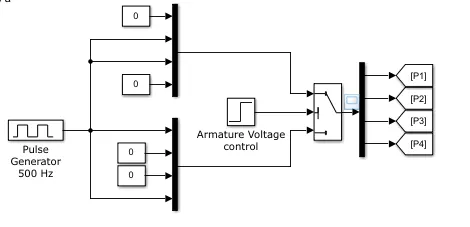
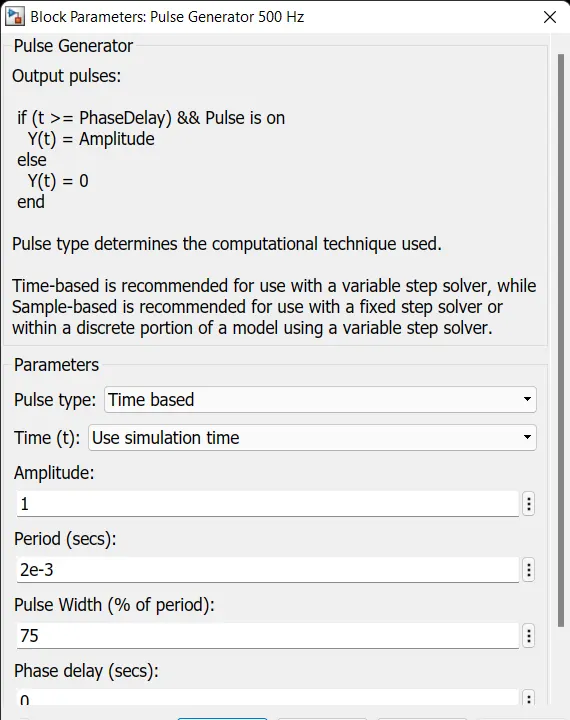
- Where the amplitude is 1 and the time period of 1 cycle is 0.002 seconds.
- The duty cycle is 75%(ratio of On time to total time) with 0 sec phase delay.
- DC VOLTAGE SOURCE
- Here the dc battery source is used as power supply for running the DC motor.
- With an amplitude of 240 V.
- And another source is used for exciting the field of the dc machine with an amplitude of 300 V.
- DC MACHINE
-
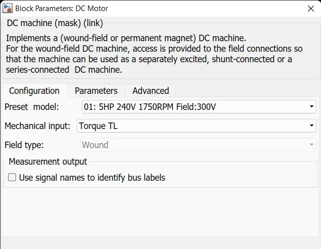
- Here the dc motor is used.
- With a specification of 5 HP 240V 1750 RPM Field:300V.
- In the block parameters we can select the different model of the machine.
- SOLVER CONFIGURATION
- Here the powergui is used as the solver for this model.
- The continious mode is selected as solver.
WORKING
- Here the simulation runtime is 1 second.
- The motor starts in the positive direction with a duty cycle of 75% (mean DC voltage of 180V). At t= 0.5 sec., the armature voltage is suddenly reversed and the motor runs in the reverse direction.
- CONTROL UNIT
- Two transistors are switched simultaneously: Q1 and Q4 or Q2 and Q3.
- FORWARD DIRECTION
- When Q1 and Q4 are fired, a positive voltage is applied to the motor and diodes D2-D3 operate as free-wheeling diodes when Q1 and Q4 are switched off.
- It occurs during the run time period of 0 - 0.5 seconds.
- During this period the voltage,current and power is entering to motor is positive .
- REVERSE DIRECTION
- When Q2 and Q3 are fired, a negative voltage is applied to the motor and diodes D1-D4 operate as free-wheeling diodes when Q2 and Q3 are switched off.
- It occurs during the run time period of 0.5 - 1 seconds.
- During this period the voltage is positive ,The current and power is entering to motor is negative .
- CALCULATION PART
- TORQUE VS SPEED
- To find the torque of the motor
-
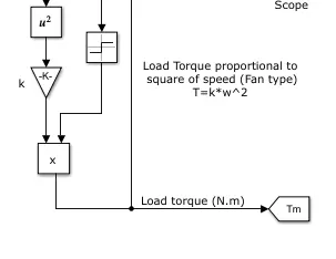
- T=K*W^2
- T--------> Torque of the motor.
- W-------> Speed of the motor in radian/sec.
- K--------> Motor constant(8.8*10^-8).
-
- To convert rad/sec to RPM
- Multiply speed with (60/(2*pi)).
- To find the torque of the motor
- TORQUE VS SPEED
OUTPUT
- IGBT & DIODE CURRENT
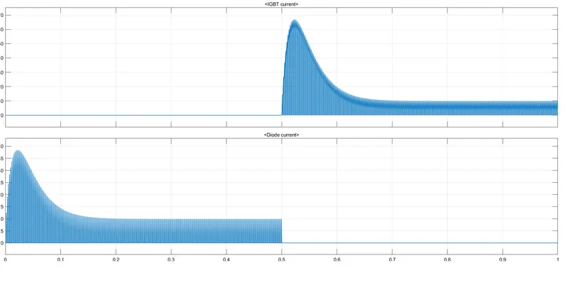
- The first graph represents the current flow through IGBT (Q3).
- The Second graph represents the current flow through Diode.
- IGBT CURRENT
- We can see that the during the first half of the simulation (upto 0.5 sec ) there is no current flow through IGBT (where the motor rotates in forward direction) .Where the Q2 & Q3 are in OFF state .
- After 0.5 sec the current suddenly rise to 65 A (at 0.52sec) in this transient period (where the motor starts to rotates in opposite direction).After some time the current reduced to 1 A(at 0.7 sec).Where the Q2 & Q3 are in ON state .
- DIODE CURRENT
- We can see that the during the first half of the simulation (upto 0.5 sec ), Where the current freewheels throught D2 & D3 (where the motor rotates in forward direction) .
- The current rises to 38 A (at 0.02 sec) during this and after some time it reaches to 9.7 A(at 0.8 sec)
- Where the D2 & D3 are in Forward bias.
- At 0.5 sec the current drops to 0 A in this transient period (where the motor starts to rotates in opposite direction).Where the D2 & D3 are in reverse bias state.
- SPEED , ARMATURE CURRENT,LOAD TORQUE
-
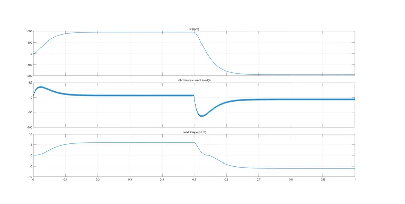
- The first graph represents the speed of the motor in RPM.
- The Second graph represents the current flow through Armature.
- The third graph represnts the Load torque of the motor in (Nm).
- SPEED (rpm)
- FORWARD ROTATION
- During the first half period (0 - 0.5 sec) the motor rotates in forward direction.
- The motor reaches its maximum positive speed as 9500 RPM at 0.28 sec .
- At 0.5 sec the motor speed starts to reduces to zero .
- Due to inertia the time taken by the motor to reach zero is 0.5 - 0.54 sec (0.04 sec).
- REVERSE ROTATION
- During the second half period (0.5 - 1 sec) the motor rotates in reverse direction.
- The motor reaches its maximum negative speed as -9500 RPM at 0.78 sec .
- The time taken by the motor to reaches its maximum speed is 0.5 - 0.78 (0.28 sec).
- FORWARD ROTATION
- LOAD TORQUE (Nm)
- FORWARD ROTATION
- During the first half period (0 - 0.5 sec) the motor rotates in forward direction.
- The motor reaches its maximum positive torque as 6 Nm at 0.26 sec .
- At 0.5 sec the motor torque starts to reduces to zero .
- Due to inertia the time taken by the motor to reach zero is 0.5 - 0.54 sec (0.04 sec).
- REVERSE ROTATION
- From this plot we can see that the motor reaches its torque to zero at 0.53 sec.After reaching zero the torque starts to increase.
- During the second half period (0.5 - 1 sec) the motor rotates in reverse direction.
- The motor reaches its maximum negative speed as -9500 RPM at 0.78 sec .
- The time taken by the motor to reaches its maximum speed is 0.5 - 0.78 (0.28 sec).
- FORWARD ROTATION
- ARMATURE CURRENT (A)
- FORWARD ROTATION
- During the first half period (0 - 0.5 sec) the motor rotates in forward direction(current is in positive direrction).
- The motor reaches its maximum positive armature current of 38 A at 0.028 sec .
- The armature current reaches its optimistic value of 6 A at 0.14 sec.
- At 0.5 sec the motor armature current is passing from positive to negative (without going to zero value) .
- REVERSE ROTATION
- During the second half period (0.5 - 1 sec) the motor rotates in reverse direction(current is in negative direction) .
- The motor reaches its maximum negative armature current of -64 A at 0.52 sec .
- The time taken by the motor to reaches its maximum armature current is 0.5 - 0.52 (0.02 sec).
- The armature current reaches its optimistic value of 9 A at 0.6 sec.
- FORWARD ROTATION
B) Comment on the armature current shoot-up from the scope results.
- From the above output we can see that the current surge in the armature .
- Where the starting current is higher than the rated one.
- By varrying the duty cycle we can reduce the current surge.
- But the drawback is the we cannt obtain the maximum output/performace of the motor.
- DUTY CYCLE = 80 %
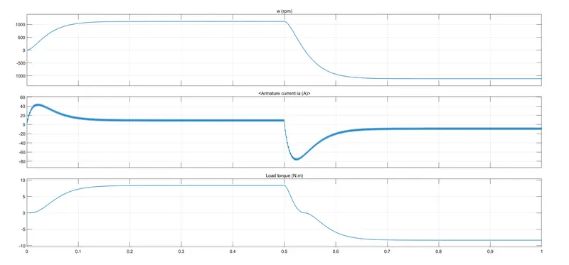
- By changing the duty cycle = 80% (higher than the default one) we can notice the change in speed,armature current and load torque.
- Here we can notice that the we got higher performance of the dc machine compared to the default model.
- Here the armature current surge is also higher .
- DUTY CYCLE = 30 %
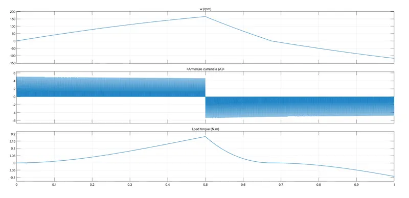
- By changing the duty cycle = 30% (lower than the default one) we can notice the change in speed,armature current and load torque.
- Here we can notice that the we got lower performance of the dc machine compared to the default model.
- Here the armature current surge is very low compared to the default one.
C) Refer to the help section of ‘The Four-Quadrant Chopper DC Drive (DC7) block’. Compare it with the H-bridge model.
FOUR QUADRANT CHOPPER
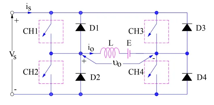
- The circuit of a four quadrant chopper or class-E chopper basically consists of four semiconductor switches CH1 to CH4 and four diodes D1 to D4.
- The four diodes are connected in anti-parallel.
- It consists of four quadrant operation.
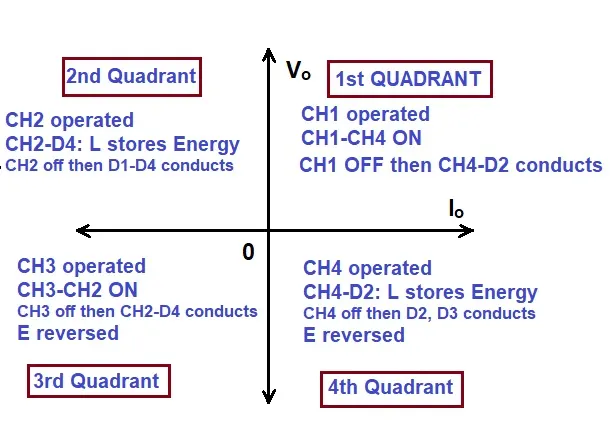
- First Quadrant Operation:
- In this quadrant both voltage,current are positive so the power is also positive.
- Here CH 1 is operated.
- CH 4 is kept ON ,CH 3 and CH 2 is kept OFF.
- When CH 1 and CH 4 is kept ON
- The load gets directly connected to the source (V0=Vs).
- Current flows from Vs - CH 1 - Load - CH 4 - Gnd.
- When CH 1 is kept OFF & CH 4 is kept ON
- The load current freewheels throught CH 4 and D2.
- Current flows from D 2 - Load - CH 4 .
- This quadrant operation is known as "Forward motoring".
- The chopper acts as step down chopper.
- Second Quadrant Operation:
- In this quadrant both voltage is positive and the current is negative so the power is negative.
- Here CH 2 is operated.
- CH 2 is kept ON ,CH 1 ,CH 3 and CH 4 is kept OFF.
- When CH 2 kept ON
- Inductor L stores energy.
- Current flows from CH 2 - Eb - Load - D 4 - CH 2.
- When CH 2 is kept OFF
- The current is fed back to the source through D1, D4.
- It should be noted at this point that Machine voltage (E+Ldi/dt) is more than the source voltage Vs (V0>Vs).
- The load current feedback to the source.
- Current flows from Load - D 1 - Vs - D 4 - La.
- This quadrant operation is known as "Forward braking".
- The chopper acts as step up chopper.
- Third Quadrant Operation:
- In this quadrant both voltage,current are negative so the power is also positive.
- Here CH 3 is operated.
- CH 1 is kept OFF ,CH 3 and CH 2 is kept ON.
- When CH 3 and CH 2 is kept ON
- The load gets directly connected to the source (V0= -Vs).
- Current flows from Vs - CH 3 - Load - CH 2 - Gnd.
- When CH 3 is kept OFF & CH 2 is kept ON
- The load current freewheels throught CH 2 and D 4.
- Current flows from D 4 - Load - CH 2 .
- This quadrant operation is known as "Reverse motoring".
- The chopper acts as step down chopper.
- Fourth Quadrant Operation:
- In this quadrant both voltage is negative and the current is positive so the power is negative.
- Here CH 4 is operated.
- CH 4 is kept ON ,CH 1 ,CH 3 and CH 2 is kept OFF.
- When CH 2 kept ON
- Inductor L stores energy.
- Current flows from D 2 - Eb - Load - CH 4 - D 2.
- When CH 2 is kept OFF
- The current is fed back to the source through D2, D3.
- It should be noted at this point that Machine voltage (E+Ldi/dt) is more than the source voltage Vs (-V0>Vs).
- The load current feedback to the source.
- Current flows from Load - D 3 - Vs - D 2 - La.
- This quadrant operation is known as "Reverse braking".
- The chopper acts as step up chopper.
-
MODEL
DISCREPTION
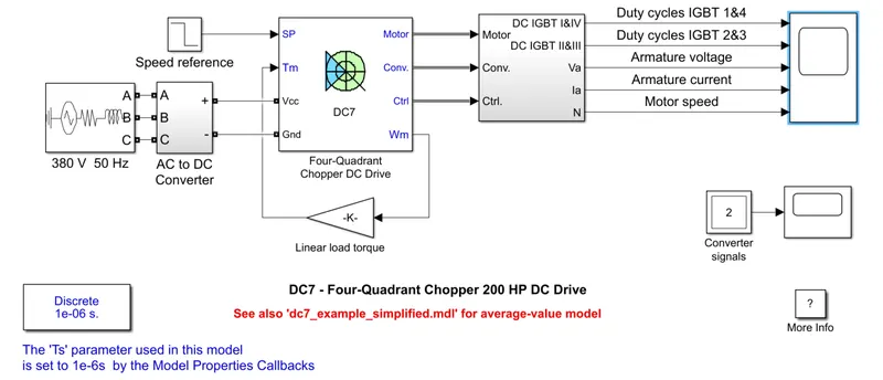
- The 200 HP DC motor is separately excited with a constant 150 V DC field voltage source.
- The armature voltage is provided by an IGBT converter controlled by two PI regulators.
- The converter is fed by a 515 V DC bus obtained by rectification of a 380 V AC 50 Hz voltage source.
- In order to limit the DC bus voltage during dynamic braking mode, a braking chopper has been added between the diode rectifier and the DC7 block.
- The first regulator is a speed regulator, followed by a current regulator.
- The speed regulator outputs the armature current reference (in p.u.) used by the current controller in order to obtain the electromagnetic torque needed to reach the desired speed.
- The speed reference change rate follows acceleration and deceleration ramps in order to avoid sudden reference changes that could cause armature over-current and destabilize the system. The current regulator controls the armature current by computing the appropriate duty ratios of the 5 kHz pulses of the four IGBT devices (Pulse Width Modulation).
- For proper system behaviour, the instantaneous pulse values of IGBT devices 1 and 4 are opposite to those of IGBT devices 2 and 3. This generates the average armature voltage needed to obtain the desired armature current.
- In order to limit the amplitude of the current oscillations, a smoothing inductance is placed in series with the armature circuit.
WORKING
- The initial bus voltage to 515 V via the GUI block .
-
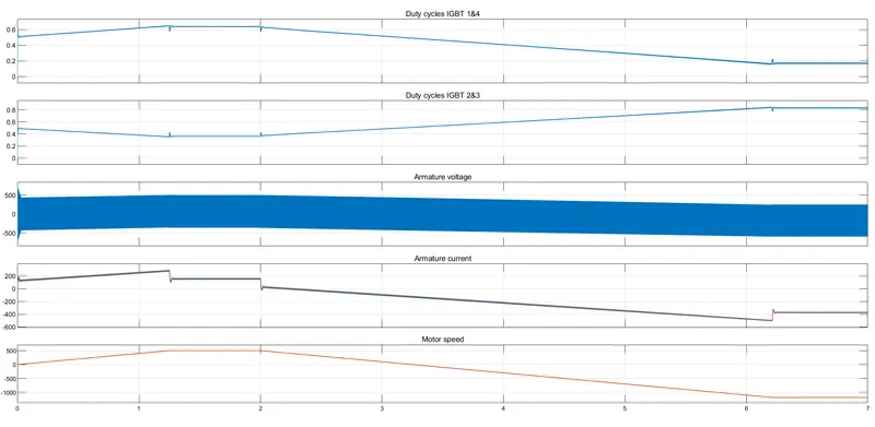
- The speed reference is set at 500 rpm at t = 0 s. Observe that the motor speed follows the reference ramp accurately (+400 rpm/s) and reaches steady state around t = 1.3 s.
- The armature current follows the current reference very well, with fast response time and small ripples. Notice that the current ripple frequency is 5 kHz.
- At t = 2 s, speed reference drops to -1184 rpm. The current reference decreases to reduce the electromagnetic torque and causes the motor to decelerate with the help of the load torque.
- At t = 2.2 s, the current reverses in order to produce a braking electromagnetic torque (dynamic braking mode). This causes the DC bus voltage to increase.
- At t = 3.25 s, the motor reaches 0 rpm and the load torque reverses and becomes negative. The negative current now produces an accelerating electromagnetic torque to allow the motor to follow the negative speed ramp (-400 rpm/s). At t = 6.3 s, the speed reaches -1184 rpm and stabilizes around its reference.
COMPARISON OF 4 QUADRANT AND H-BRIDGE
| S.NO | H-BRIDGRE | 4 QUADRANT |
| 1. | Simple design | Complex design |
| 2. | It consists of four transistors and diodes. | It consists of four transistors and diodes. |
| 3. | Gate signal used to trigger the converters are continuous signal. | Gate signal used to trigger the converters are dicrete signal. |
| 4. | Motor is operated in only two modes. | Motor is operated in all four modes. |
| 5. |
The achievable modes are
|
The achievable modes are
|
| 6. | Used in low performance machines ,Which requires basic control. | Used in high performance machines,Which requires better control. |
2.Develop a 2-quadrant chopper using simulink & explain the working of the same with the relevant results. (Refer to article - Multiquadrant operation of motor)
MODEL
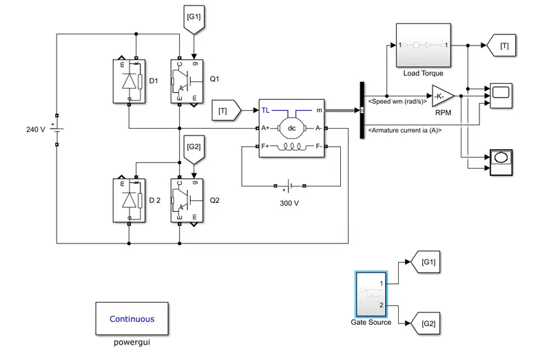
BLOCKS USED
- IGBT
- This model consists of 2 IGBT , which is represented as Q1,Q2.
- The forward voltage Vf is developed between collector and emitter (in the range of 1 V). Therefore, the IGBT block can be used to model the BJT device.
- The gate pulse is triggered by the pulse generator.
- GATE PULSE
- By using the pulse generator the gate pulse are given as G1,G2.
-
-
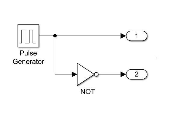
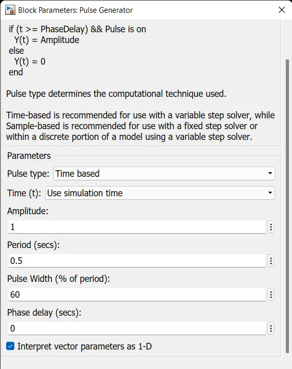
- Where the amplitude is 1 and the time period of 1 cycle is 0.5 seconds.
- The duty cycle is 60%(ratio of On time to total time) with 0 sec phase delay.
- DC VOLTAGE SOURCE
- Here the dc battery source is used as power supply for running the DC motor.
- With an amplitude of 240 V.
- And another source is used for exciting the field of the dc machine with an amplitude of 300 V.
- DC MACHINE
-
- Here the dc motor is used.
- With a specification of 5 HP 240V 1750 RPM Field:300V.
- In the block parameters we can select the different model of the machine.
-
- LOAD TORQUE
- To find the torque of the motor
-
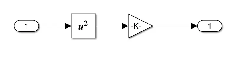
- T=K*W^2
- T--------> Torque of the motor.
- W-------> Speed of the motor in radian/sec.
- K--------> Motor constant(8.8*10^-8).
-
- To convert rad/sec to RPM
- Multiply speed with (60/(2*pi)).
- To find the torque of the motor
- SOLVER CONFIGURATION
- Here the powergui is used as the solver for this model.
- The continious mode is selected as solver.
WORKING
- Here the simulation runtime is 1 second.
- The motor starts to rotates with a duty cycle of 75% (mean DC voltage of 180V). At t= 0.5 sec., the armature current is suddenly reversed and the motor goes to braking mode.
- CONTROL UNIT
- Two transistors are switched simultaneously: Q1 and Q2.
- FORWARD MOTORING MODE
- When Q1 is fired, a positive voltage is applied to the motor (Vs=V0).
- When Q1 is switched off ,The diodes D2 operate as free-wheeling diodes(V0=0).
- It occurs during the run time period of 0 - 0.3 seconds & 0.5 - 0.8 seconds.
- During this period the voltage,current,power entering to motor is positive .
- Current flows from Source to load.
- FORWARD BREAKING MODE
- When Q2 is fired, a positive voltage is applied to the motor and diodes D1 is operated as free-wheeling diodes when Q2 is switched off.
- It occurs during the run time period of 0.3 - 0.5 seconds & 0.8 - 1 seconds.
- During this period the voltage is positive ,The current and power is entering to motor is negative .
- Current flows from Load to source.
OUTPUT
- SPEED , ARMATURE CURRENT,LOAD TORQUE
-
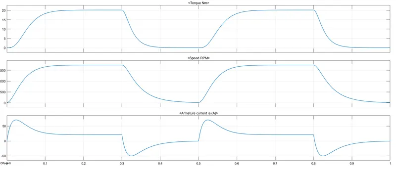
- The first graph represents the Load torque of the motor in (Nm).
- The Second graph represents the speed of the motor in RPM.
- The third graph represnts the current flow through Armature.
- SPEED (rpm)
- FORWARD MOTORING MODE
- During the first half period (0 - 0.3 sec) the motor rotates in forward direction.
- The motor reaches its maximum positive speed as 1750 RPM at 0.12 sec .
- At 0.3 sec the motor enters into breaking mode.
- FORWARD BREAKING MODE
- During the second half period (0.3 - 0.5 sec) the motor rotates in reverse direction.enters into breaking mode.
- Due to inertia the time taken by the motor to reach 12 RPM is 0.3 - 0.5 sec (0.2 sec).
- The motor reaches its breaking speed as 12 RPM at 0.5 sec .
- The time taken by the motor to reaches its maximum breaking speed is 0.3 - 0.5 (0.2 sec).
- FORWARD MOTORING MODE
- LOAD TORQUE (Nm)
- FORWARD MOTORING MODE
- During the first half period (0 - 0.3 sec) the motor rotates in forward direction.
- The motor reaches its maximum positive torque as 20 Nm at 0.14 sec .
- At 0.3 sec the motor torque starts to reduces to zero .
- Due to inertia the time taken by the motor to reach zero is 03- 0.5 sec (0.2 sec).
- FORWARD BREAKING MODE
- From this plot we can see that the motor reaches its torque to zero at 0.5 sec.
- During the second half period (0.3 - 0.5sec) the motor operates in breaking mode.
- The time taken by the motor to reaches its maximum speed is 0.3 - 0.5 (0.2 sec).
- FORWARD MOTORING MODE
- ARMATURE CURRENT (A)
- FORWARD MOTORING MODE
- During the first half period (0 - 0.3 sec) the motor rotates in forward direction(current is in positive direrction).
- The motor reaches its maximum positive armature current of 70 A at 0.025 sec .
- The armature current reaches its optimistic value of 22 A at 0.14 sec.
- At 0.303 sec the motor armature current is passing from positive to negative (without going to zero value) .
- FORWARD BREAKING MODE
- During the second half period (0.3 - 0.5 sec) the motor rotates in reverse direction(current is in negative direction) .
- The motor reaches its maximum negative armature current of -50 A at 0.32 sec .
- The time taken by the motor to reaches its maximum armature current is 0. - 0.32 (0.02 sec).
- The armature current reaches its optimistic value of 3 A at 0.4 sec.
- FORWARD MOTORING MODE
-
- SPEED VS TORQUE
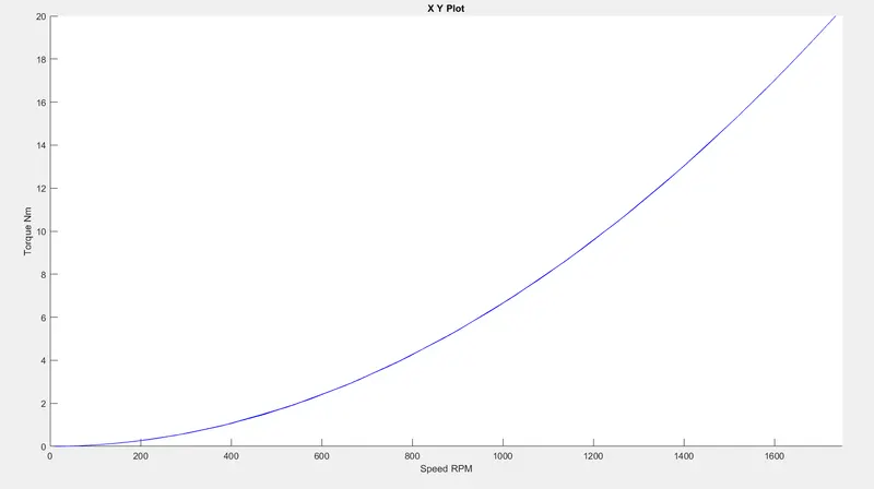
- Here the fan type of load is used .
- So the torque(Nm) is proportional to speed(RPM).
- T = K*w^2.
3) Explain in a brief about operation of BLDC motor.
BLDC MOTOR
-
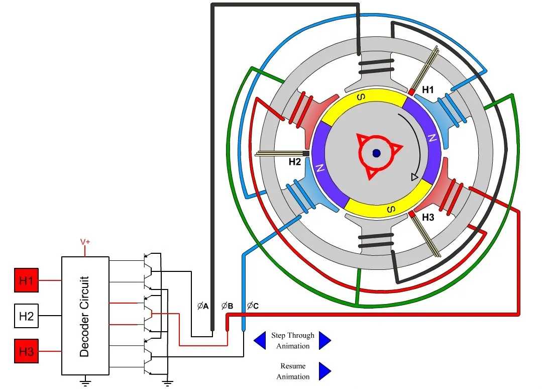
- A Brushless DC Motor, BLDC accomplishes commutation electronically using rotor position feedback to determine when to switch the current.
- The BLDC motor is electrically commutated by power switches instead of brushes.
- BLDC has no brushes and commutator for having unidirectional torque rather integrated inverter / switching circuit is used to achieve unidirectional torque.
- It is also known as Electronically Commutated Motors.
Construction of a BLDC Motor:
- BLDC Stator:
-
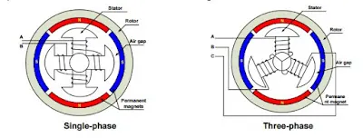
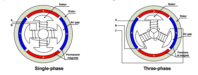
- There are three types of the BLDC motor:
- Single-phase
- Three-phase.
- Stator for each type has the same number of windings. The single-phase and three-phase motors are the most widely used.
- The simplified cross section of a single-phase and a three-phase BLDC motor .
- The rotor has permanent magnets to form two magnetic pole pairs, and surrounds the stator, which has the windings.
- SINGLE PHASE STATOR
- A single-phase motor has one stator winding wound either clockwise or counter-clockwise along each arm of the stator to produce four magnetic poles.
- THREE PHASE STATOR
- A three phase BLDC motor has three windings. Each phase turns on sequentially to make the rotor revolve.
-
- Rotor:
- A rotor consists of a shaft and a hub with permanent magnets arranged to form between two to eight pole pairs that alternate between north and south poles.
-
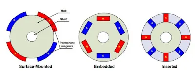
- The rotor position is identified by the help of hall effect sensor.
- From the above figure we can find the types of rotor windings:
- Surface Mounted.
- Embedded.
- Inserted.
- OUTRUNNER/SURAFCE MOUNTED
- The field magnet is a drum rotor which rotates around the stator.
- This style is preferred for applications that require high torque and where high rpm isn’t a requirement.
- INRUNNER/INSERTED
- The stator is a fixed drum in which the field magnet rotates.
- This motor is known for producing less torque than the out runner style, but is capable of spinning at very high rpm.

WORKING OF BLDC MOTOR
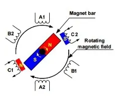
- BLDC Motor operation is based on the attraction or repulsion between magnetic poles.
- Using the three-phase motor , the process starts when current flows through one of the three stator windings and generates a magnetic pole that attracts the closest permanent magnet of opposite pole.
-
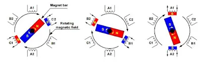
- The rotor will move if the current flows to an adjacent winding.
- Sequentially charging each winding will cause the rotor to follow in a rotating field.
- The torque is depends on the current amplitude and the number of turns on the stator windings, the strength and the size of the permanent magnets, the air gap between the rotor and the windings, and the length of the rotating arm.
-


Advantage of BLDC Motor:
- Higher efficiency and reliability.
- Lower acoustic noise.
- Smaller and lighter.
- Greater dynamic response.
- Better speed versus torque characteristics.
- Higher speed range.
- Longer life.