Week - 4
1.CONTROL LOGIC OF WASHING MACHINE USING STATEFLOW
OBJECTIVE
To Implement control logic of a “washing machine” using Stateflow as per given sequence
MODEL
BLOCKS USED
- POWER SWITCH
- By using power switch we can turn ON/OFF the power source .
- The Switch is connected to the constant block(POWER).
- The switch parameter is set in the way of ON - '1' & OFF - '0'.
- WATER SWITCH
- By using water switch we can turn ON/OFF the water source.
- The Switch is connected to the constant block(WATER).
- The switch parameter is set in the way of ON - '1' & OFF - '0'.
- POWER LAMP
- By using power lamp we know the power switch is ON/OFF.
- The lamp is connected to the constant block(POWER).
- If the power switch is 'ON' the lamp glows as GREEN colour.
- If the power switch is 'OFF' the lamp does not glows .
- WATER LAMP
- By using water lamp we know the power switch is ON/OFF.
- The lamp is connected to the constant block(WATER).
- If the water switch is 'ON' the lamp glows as GREEN colour.
- If the water switch is 'OFF' the lamp does not glows .
- FINISHED LAMP
- By finished water lamp we know the washing process is done.
- The lamp is connected to the event Finished.
- If all the events are done the lamp glows as RED colour.
- If the process is incomplete ,the lamp doesn't glow.
- SCOPE
- By the help of scope block we can visualize the output of the Washing machine.
- Here the stop time is 400 seconds.
MODEL AS STATE FLOW
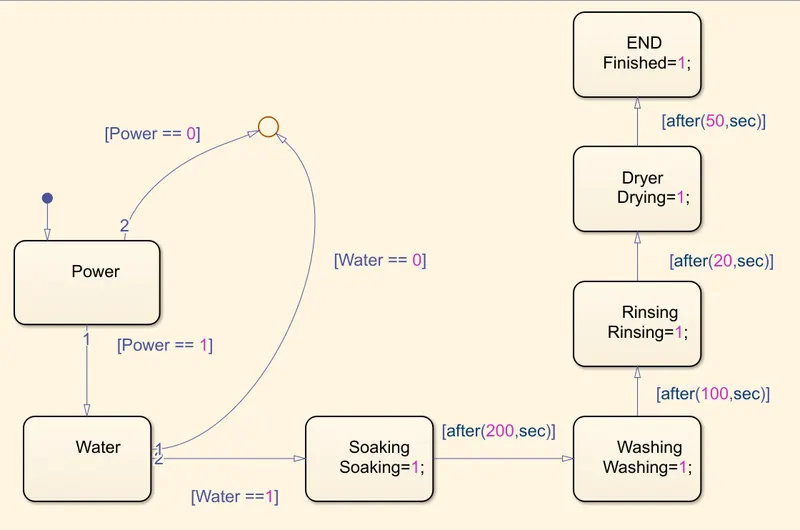
EVENTS USED
- POWER
- It is the strating of the event if the power is given (Power ==1) it goes to the next event.
- If the power is not given (Power ==0)it is given to the junction which is out of loop.
- WATER
- It is the second stage of the event if the water supply is given (Water ==1) it goes to the next event.
- If the water is not given (Water ==0) it is given to the junction which is out of loop.
- SOAKING
- It is the event where the clothes are soaked in water for 200 seconds .
- After 200 seconds it enters to the next state .
- WASHING
- It is the state where the cloths are washed for 100 seconds .
- RINSING
- It is the state where the soap is washed away for 20 seconds.
- DRYER
- It is the state where the washed clothes are dried for 50 seconds.
- END
- It is the end of the washing event where the lamp will glow .
WORKING
- POWER & WATER OFF
- In this condition where both power & water supply is not given.
- The event will terminate before starting any event.
- POWER OFF & WATER ON
-
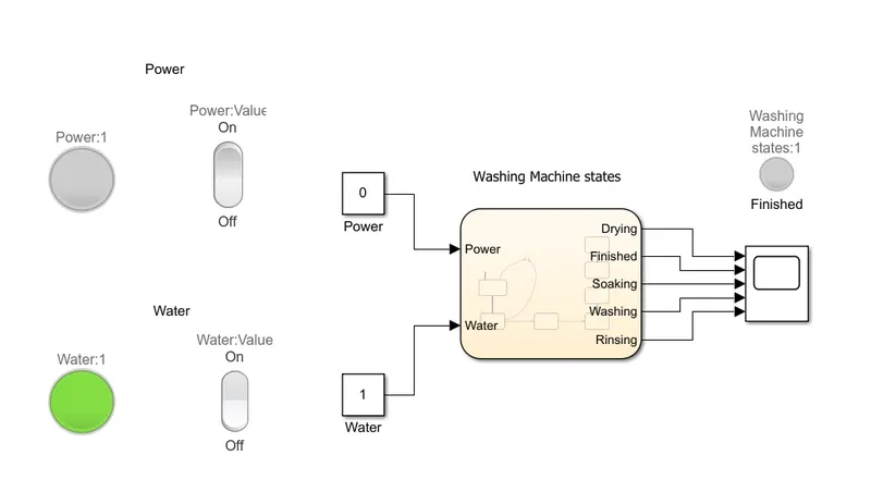
- In this condition where the power supply is not given,Only the water supply is given.
- The event will terminate before starting any event.
-
- POWER ON & WATER OFF
-
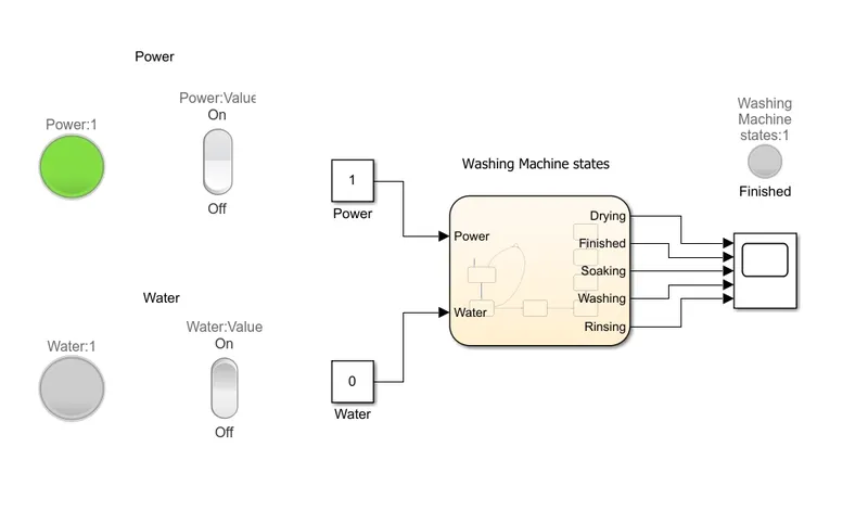
- In this condition where power supply is given,Water supply is not given.
- The event will terminate before starting any event.
-
- POWER & WATER ON
- In this condition where both power & water supply is given.
- The event will start by entering into the soaking state for 200 seconds.
- Then the next event washing will start for 100 seconds.
- Then the next event rinsing will start for 20 seconds.
- Then the Final event drying will start for 50 seconds.
- After the dryier event all the events are ended and it is intimated by the lamp.
OUTPUT
-
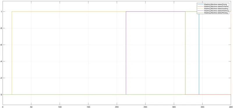
- It is the graphical representation of the washing event.
- When the power & water supply is given the soaking event is started for the period of 200 seconds which is represented by the orange plot.
- After the soaking event is ended,the washing event is started for the period of 100 seconds which is represented by the violet plot.
- After the washing event is ended,the rinsing event is started for the period of 20 seconds which is represented by the green plot.
- After the rinsing event is ended,the drying event is started for the period of 50 seconds which is represented by the blue plot.
2.SIMULINK CHART FOR GEAR SHIFT
OBJECTIVE
To make a Simulink chart for the “Gear shift”
MODEL
BLOCKS USED
- REPEATING SEQUENCE
- It is used to varry the speed range during the run time of the simulation.
- IGNITION
- It is also a connstant block which is used to ON/OFF the engine.
- If Ignition = 1 it is in ON state.
- If ignition = 0 it is in OFF state.
- BREAK
- It is a constant block which is used as input for brake.
- If Brake = 0 then the brake is OFF.
- If Brake = 1 then the brake is ON.
- IGNITION LAMP
- It is used as an indicator which shows the Ignition is ON/OFF.
- If the Ignition = 1 it is ON condition ,it shows as Green color.
- If the Ignition =0 it is OFF condition,it shows as Red color.
- BREAK LAMP
- It is used as an indicator which shows the Break is ON/OFF.
- If the Break = 1 it is ON condition ,it shows as Red color.
- If the Break =0 it is OFF condition,it shows as Green color.
- SCOPE
- It is used to study the output of the simulation.
MODEL AS STATE FLOW
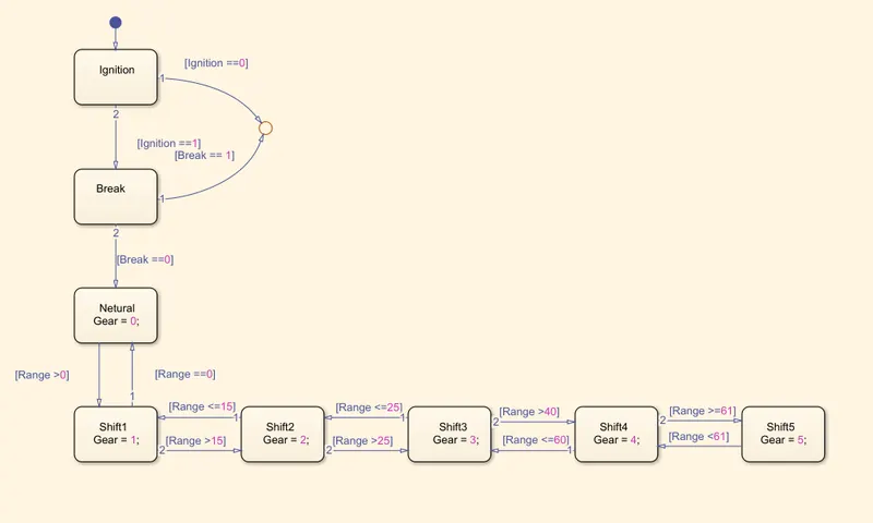
EVENTS USED
- IGNITION
- It is the starting of the event if the ignition is given (IGNITION ==1) it goes to the next event.
- If the ignition is not given (Ignition ==0)it is given to the junction which is out of loop.
- BREAK
- It is the second stage of the event if the break is not applied (Break ==0) it goes to the next event.
- If the break is applied (BREAK ==1)it is given to the junction which is out of loop.
- NEUTRAL
- It is the gear position .
- When the 'RANGE==0',which gives a values as 'GEAR =0'.
- SHIFT1
- It is the gear position .
- When the range is above 0 - 15 ,which gives a values as 'GEAR =1'.
- If the speed range is below '1',it shift down to the gear position 0.
- SHIFT2
- It is the gear position .
- When the range varies from 16 - 25 ,which gives a values as 'GEAR =2'.
- If the speed range is below '16' ,it shift down to the gear position 1.
- SHIFT3
- It is the gear position .
- When the range varies from 26 - 40 ,which gives a values as 'GEAR =3'.
- If the speed range is below '26' ,it shift down to the gear position 2.
- SHIFT4
- It is the gear position .
- When the range varies from 41 - 60 ,which gives a values as 'GEAR =4'.
- If the speed range is below '41' ,it shift down to the gear position 3.
- SHIFT5
- It is the gear position .
- When the rangeis above 60 ,which gives a values as 'GEAR =5'.
- If the speed range is below '60' ,it shift down to the gear position 4.
WORKING
- IGNITION & BREAK ON
- In this case both Ignition & Break is ON .
- The event will terminate at the Brake event and send to the junction.
- IGNITION & BREAK OFF
- In this case both Ignition & Break is OFF .
- The event will terminate at the Ignition event itself and send to the junction.
- IGNITION - OFF & BREAK -ON
- In this case Ignition is OFF & Break is ON .
- The event will terminate at the Ignition event itself and send to the junction.
- IGNITION - ON & BREAK - OFF
- In this case Ignition is On & Break is OFF .
- The event will start by entering into Netural event it checks the condition if the 'Range ==0' then 'GEAR=0' is shown in display block.
- If 'Range is 1-15' then it will enter into Shift1 event then 'GEAR=1' is shown in display block.
- If 'Range is 16-25' then it will enter into Shift2 event then 'GEAR=2' is shown in display block.
- If 'Range is 26-40' then it will enter into Shift3 event then 'GEAR=3' is shown in display block.
- If 'Range is 41-60' then it will enter into Shift4 event then 'GEAR=4' is shown in display block.
- If 'Range is above 60' then it will enter into Shift5 event then 'GEAR=5' is shown in display block.
OUTPUT
-
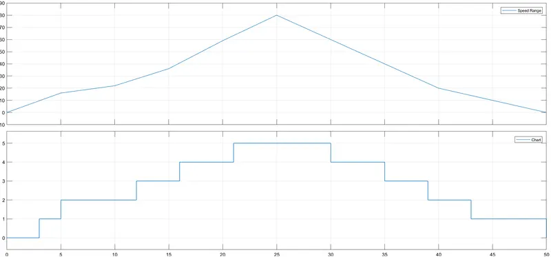
- The output can be verified using the scope block.
- Where the first plot represents the Speed VS Time , where the X-axis represents 'Time' and Y-axis represents 'Speed Range'.
- The second plot represents the Gear position VS Time , where the X-axis represents 'Time' and Y-axis represents 'Gear position'.