Week -2
1.Make a Simulink model of Doorbell using solenoid block
OBJECTIVE
To make a simulink model of doorbell using solenoid block,where the switch is closed for 2 seconds and then released.
MODEL
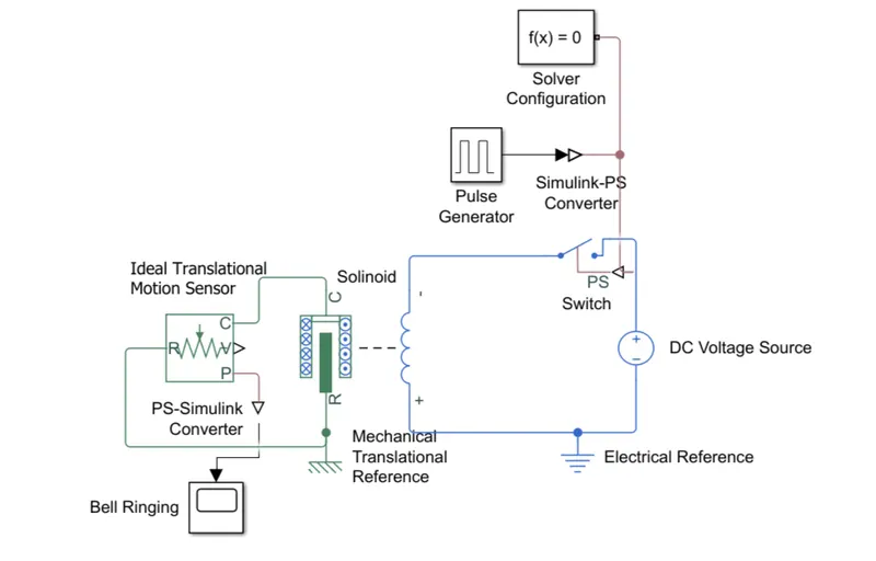
BLOCKS USED
- PULSE GENERATOR
- The role of the pulse generator is to 'ON' the switch for 2 seconds because the phase delay is given as 2 seconds.
- The pulse generator is connected to the Simulink-PS converter.
- SIMULINK-PS CONVERTER
- By using Simulink-PS converter we can directly connect the simulink and the physical system.
- Here the simulink component is Pulse generator.
- And physical system is Switch.
- SOLVER CONFIGURATION
- It specifies the solver parameters that requires for your physical network represented by a connected simscape block.
- SWITCH
- If the switch is closed ,It will connect the solinoid and the supply(ON state).
- If the switch is open ,It will disconnect the solinoid and the supply(OFF state).
- DC VOLTAGE SOURCE
- The DC source is connected in series with both solinoid and the switch.
- The DC source will make the solinoid as electromagnet when the switch is closed.
- Here the supply is given as 1V.
- SOLINOID
- The solinoid is connected in series with the switch.
- When the solinoid becomes electromagnet then the Plunger will move from R to C .
- ELECTRICAL REFFERENCE
- It is an electrical ground which is used to connect the electrical elements in the model.
- IDEAL TRANSLATIONAL MOTION SENSOR
- This block measures velocity or displacement in a mechanical translational network.
- It measures the motion of plunger in the solenoid.
- MECHANICAL TRANSLATIONAL REFERENCE
- This block represents a mechanical translational reference point, that is, a frame or a ground.
- PS-SIMULINK CONVERTER
- By using PS-Simulink converter we can directly connect the physical system and the simulink.
- Here the simulink component is scope.
- And physical system is ideal translational motion sensor.
- SCOPE
- By using scope we can observe the ringing of the bell.
OBSERVATION
- When the switch is closed the solinoid is exicited by the dc source.
- The switch is controlled by the pulse generator with an phase delay of 2 secs and the pulse width of 50%.
- The output of the solinoid is given to the Ideal translational motion sensor to sense the motion of the plunger from R to C.
- The ringing of the bell is observed by the help of scope.
OUTPUT
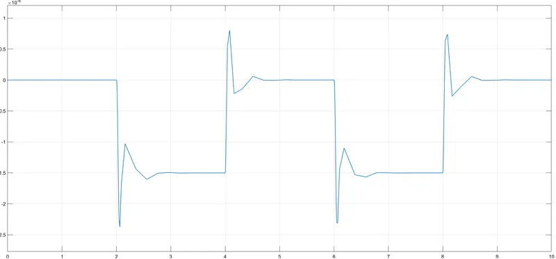
- The silulation stop time is 10 seconds.
- From the plot we can oberserve that when the switch is closed the solenoid becomes electromanget by the help of the DC source .
- Then the plunger will morves from R to C to ring the bell.
2.SIMULINK MODEL FOR FAN OPERATING SYSTEM USING THERMISTOR
OBJECTIVE
To make a simulink model for fan operating system using thermistor when
Temperature source: 20 °C from 0 to 10 seconds, 27 °C from 10 to 30 seconds, 23 °C from 30 to 50 seconds
Fan conditions: ON if the temperature above 25 °C, OFF otherwise.
MODEL
The simulation stop time is 60 seconds 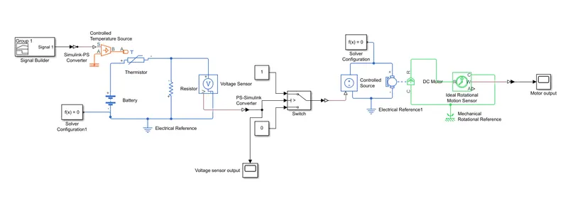
SOME COMMONLY USED BLOCKS
- SIMULINK-PS CONVERTER
- By using Simulink-PS converter we can directly connect the simulink and the physical system.
- Here the simulink component is Signal bulider block.
- And physical system is Controlled temperature source.
- Here the simulink component is Controlled source.
- And physical system is Switch.
- THERMAL REFFERENCE
- Represents a reference point in a thermal network where the temperature is equal to absolute zero.
- ELECTRICAL REFFERENCE
- It is an electrical ground which is used to connect the electrical elements in the model
- SOLVER CONFIGURATION
- It specifies the solver parameters that requires for your physical network represented by a connected simscape block.
- PS-SIMULINK CONVERTER
- By using PS-Simulink converter we can directly connect the physical system and the simulink.
- Here the simulink component is switch.
- And physical system is Voltage sensor.
- MECHANICAL ROTATIONAL REFFERENCE
- This block represents a mechanical rotational reference point, that is, a frame or ground.
BLOCKS USED
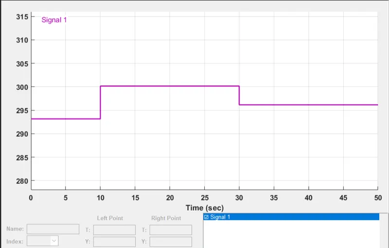
- SIGNAL BUILDER BLOCK
- Create and generate interchangeable groups of signals whose waveforms are piecewise linear.
- Here the temperature is represented as kelvin.
- The X axis is Time which is represented as sec.
- The Y axis is Temperature which is represented as Kelvin.
- The inputs are
- From 0-10sec the temperature is at 293.15K
- From 10-30sec the temperature is at 300.15K
- From 30-50sec the temperature is at 296.15K
- CONTOLLED TEMPERATUE SOURCE
- It is an ideal energy source in the thermal network
- s - Physical signal port where the signal or supply is given
- A - is grounded by thermal refference.
- B - is the diffence of A & S where the output is received.
- THERMISTOR
- There are two types of thermistor are used NTC(Negative thermal coefficient) & PTC(positive thermal coefficient).
- Here the thermistor used is NTC , the properties of this thermistor is As the temperature rises the resistance of the thermistor is decreases.
- BATTERY
- It is an DC source.
- Which is used as an supply for the thermistor to work.
- RESISTOR
- The resistance is connected parallel to the Voltage sensor.
- VOLTAGE SENSOR
- The voltage sensor is used to measure the potential difference between the thermistor.
- V is the physical signal port that outputs voltage value.
- VOLTAGE SENSOR OUTPUT(SCOPE1)
- By using the scope we can monitor the output of the voltage sensor.
- It is used to set the thresold value of the switch.
- CONSTANT
- Here two constant blocks are used 1 & 0.
- Which is used as First and second input for the switch.
- SWITCH
- The first and third are data input.
- The second is the conrtol input.
- When the condition is specified, The switch will select the first or second input.
- CONTROLLED SOURCE
- It is an idel voltage source that is powerful enough to maintain the specified voltage.
- At its output regardless of the current passing through it.
- DC MOTOR
- Here the DC motor is used to represent the fan.
- IDEAL ROTATIONAL MOTION SENSOR
- This block measures angular velocity or angle in a mechanical rotational network.
- MOTOR OUTPUT(SCOPE 2)
- By using the scope we can monitor the ON/OFF of the fan
- If the fan is ON it shows the value as 1.
- If the fan is OFF it shows the value as 0.
OBSERVATION
- The input is given by the help of the signal block builder as per the given statement.
- Then the signal is processed by the Controlled temperature source where the signal is converted into thermal source.
- The output of the controlled thermal source is given to the Thermistor which is powerd by the battery source.
- The output of the thermistor is measured by an voltage sensor.
- The measured voltage signal is given to the switch.
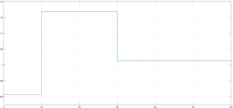
- The switch will ON/OFF the fan by the conditions specified to it.
- The conditions which is given to the switch is obatined by scope which shows the output of the voltage sensor.
- The output of the switch is given to the controlled source which is used to power the DC motor which is considered as Fan.
- The ideal rotational motion sensor is used to sense the rotational of the motor .
- Where the output is observed by the Scope
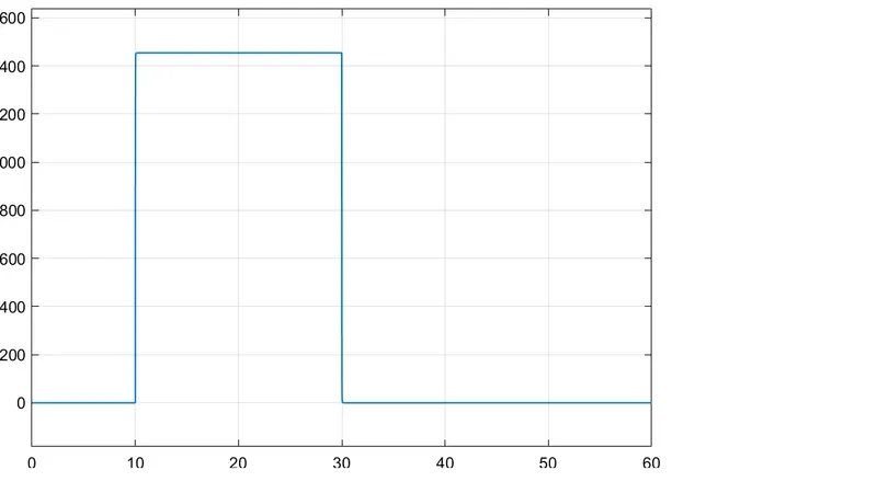
- From the graph we can observe that X axis is Time which is reprented as 'Seconds' and Y axis is fan RPM.
- The fan is OFF during the period of 0-10seconds when the temperatue is 20°C.
- The fan is ON during the period of 10-30seconds when the temperatue is 27°C.
- The fan is OFF during the period of 30-50seconds when the temperatue is 23°C.