Project
BAJA ALL TERRAIN VEHICLE (ATV) MODEL WITH CONTINUOUSLY VARIABLE TRANSMISSION
OBJECTIVE
To study and write the detailed report about BAJA ATV model with Continuously Variable Transmission(CVT).
BLOCKS USED
DASHBOARD
- RPM
- It shows the RPM value in the graphical representation.
- It is connected to the Engine sensor(Ideal motion sensor).
- BRAKE INPUT
- It is a knob input which is connected to constant block(Brake input).
- By using this block we can varry the input brake during the simulation.
- THROTTLE INPUT
- It is a knob input which is connected to constant block(Throttle input).
- By using this block we can varry the input throttle during the simulation.
- VELOCITY
- It shows the velocity value in the graphical representation.
- It is connected to the output of the Vechicle body.
SIMSCAPE MODEL
- BRAKE INPUT
- This block is used to varry the brake input.
- It is connected to the Brake drum which is present in the vechicle body sub-block.
- It is used to stop or reduce the velocity of the vechicle.
- THROTTLE INPUT
- This block is used to varry the throttle input.
- It is connected to the Generic Engine block.
- It is used to accelerate the vechicle.
- GENERIC ENGINE
- It is a engine block where the engine torque,limits are predefined.
- Here the inputs are taken from the plot Torque VS Engine speed as tabulated value
- ENGINE SENSOR
-
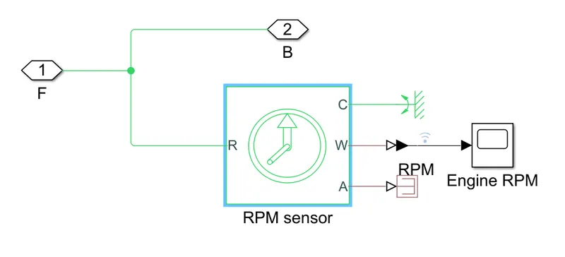
- It is the sub block.
- Which is used to measure the RPM of the generic engine.
-
- CVT RATIO
- It is used in only open loop model.
- It is Signal bulider block.
- Which is used to set the gear ratio for the CVT.
- CVT
-
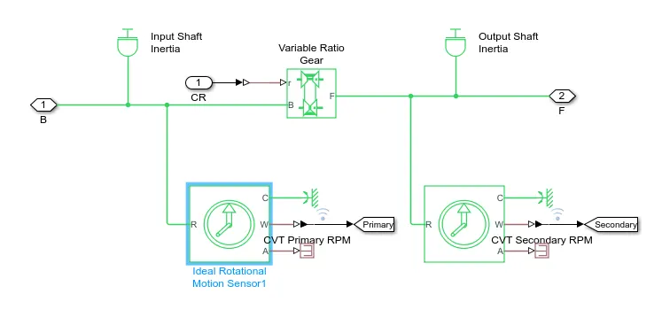
- It is the sub-block ,which consists os primary and secondary shaft and the variable ratio gear.
-
- VARIABLE RATIO GEAR
- It is used to change the variator perimeter.
- Which leads to speed reduction and speed override.
- IDEAL ROTATIONAL SENSOR
- This block is used to sense the RPM of the primary and secondary shaft.
- GEAR RATIO
- This block is used to connect the CVT to the vechicle body.
- It is the fixed gear ratio.
- VECHICLE BODY
-
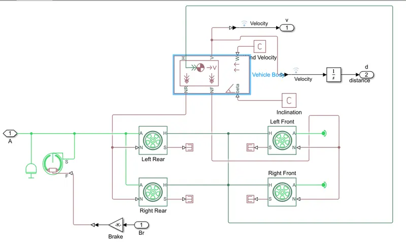
- It is a sub-block which consists of Four wheel blocks,brake drum,inertia.
- Here the wheels used are common wheels.
- The role of the vechicle body is to apply the mass,drag,pitch values as per the real vechicle.
-
- OUTPUT/VEHICLE SPEED
- This is the output block(Scope).
- Where we can plot the vechicle speed, throttle,brake as a graphical manner.
- CVT SHAFT SPEED
- This is the output block(Scope).
- Where we can plot the primary and seconday shaft as a graphical manner.
MODEL OF CVT OPEN LOOP
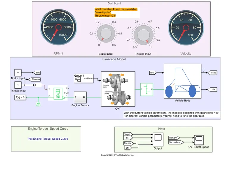
WORKING OF OPEN LOOP
- When the Throttle and brake are given during the simualtion.
- The values got from the image(Torque VS Speed curve) and the Throttle value is given to the generic sensor.
- The RPM of the engine is measured by the Engine sensor sub-block.
- The signal builder block is used to provide the CVT gear ratio for open loop system.
- If the radius of the primary pully increases than secondary pully (Rp>Rs) it results in the Overdrive action.
- The simple gear ratio is used to connect the engine and CVT block after speed reduction is done.
- Here the simple gear ratio is 4 for better performance
- In the CVT block The primary shaft inertia & Secondary shaft inertia represents the ptim,ary & secondary pully.
- If the radius of the primary pully decreases than secondary pully (Rp<Rs) it results in the speed reduction action.
- Vechicle body is the sub-block where we can enter the niumber of wheels, mass,drag,pitch for the vechicle.
- The drawback of the open loop method is the CVT ration is given it is not from the output velocity of the vehicle so it is not suited for the real time.
MODEL OF CVT CLOSED LOOP
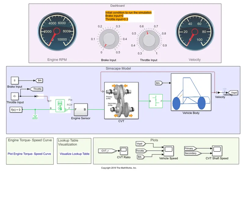
WORKING OF CLOSED LOOP
- The working of the closed loop is same as the open loop .
- But here the CVT ratio is taken from the ojutput veleocity of the vechicle .
- The CVT gear ratio is given according to the output velocity of the vechicle.
- Which overcomes the drawback of the open loop model.
OUTPUT
-
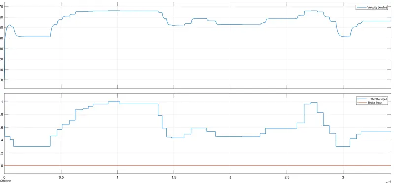
- From the plot we can understand that the brake is not applied.
- The output velocity is depends on the throttle (input).